FUNCTION GENERATOR-SERIES
INSTRUCTION MANUAL
13
4. FUNCTION DESCRIPTION
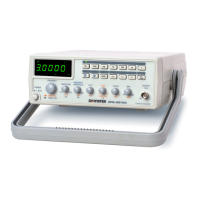
1. Power Switch Connect the AC power, then press power switch.
2. Gate Time
Indicator
Press the power switch, Gate time indicator will start
to flash (the gate time of internal counter is 0.01
second).
2a. Gate Time
Selector
Press this key to change gate time when use external
counter mode. The change order is according to 0.01s,
0.1s, 1s, 10s cycle by pressing these keys.
3. Over Indicator In the external counter mode, the indicator is
illuminated when the output frequency is greater than
the range selected.
4. Counter Display Shows the external frequency by 6 × 0.3" green
display, and shows the internal frequency by 5 × 0.3
green display.
5. Frequency
Indicator
Indicate the current frequency value.
6. Gate Time
Indicator
Indicate the current Gate time (external. counter mode
use only).
7. Frequency Range
Selector
To select the required frequency range by pressing the
relevant push button on the panel as shown in
Table 1 and Table 2.
FUNCTION GENERATOR-SERIES
INSTRUCTION MANUAL
14
Table 1(for GFG-8215A/8216A/8217A/8219A)
Push bottom 1 10 100 1k 10k 100k 1M
Frequency Range
0.3Hz
∣
3Hz
3Hz
∣
30Hz
30Hz
∣
300Hz
300Hz
∣
3kHz
3kHz
∣
30kHz
30kHz
∣
300kHz
300kHz
∣
3MHz
Table 2(for GFG-8250A/8255A)
Push bottom 1 10 100 1k 10k 100k 1M
Frequency Range
0.5Hz
∣
5Hz
5Hz
∣
50Hz
50Hz
∣
500Hz
500Hz
∣
5kHz
5kHz
∣
50kHz
50kHz
∣
500kHz
500kHz
∣
5MHz
8. Function Selector Press one of the three push buttons to select the desired
output waveform.
9. Duty Function Pull out and rotate the knob to adjust the duty cycle o
the waveform.
10. TTL/CMOS Selector
When push in the knob, the BNC terminal of
20
will
output a TTL compatible waveform. If pull out and
rotate the knob can adjust the CMOS compatible output
(5-15Vpp) from the output of BNC
20
.
11. DC Offset Control Pull out the knob to select any DC level of the
waveform between ± 10V, turn clockwise to set a
positive DC level waveform and invert for a negative
DC level waveform.
12. Output Amplitude
Control with
Attenuation
Operation
Turn clockwise for MAX. output and invert for a –20dB
output. Pull the knob out for an additional 20dB output
attenuation.
www. .com
information@itm.com1.800.561.8187
 Loading...