After setting the switches and control knobs as mentioned, connect the power cord to the AC line outlet, then follow the
procedure describes as follows:
1)
Press the POWER switch and make sure that the power LED is turned on. In about
20
seconds, a trace will appear on
the CRT screen. If no trace appears in about
60
seconds, counter check the switch and control setting.
2)
Adjust the trace to an appropriate brightness and image with INTEN and FOCUS control knob respectively.
3)
Align the trace with the horizontal central line of the graticule by adjusting the CH1 POSITION control knob and
TRACE ROTATION control knob(adjusted with screwdriver).
4)
Connect the probe to the CHI INPUT terminal and apply 2Vp-p CALIBRATOR signal to the probe tip.
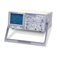
5)
Set the AC-GND-DC switch to AC, a waveform will be displayed on the CRT
0
screen as shown in the figure 5-1.
FIG.
5-1
6)
Adjust the FOCUS control knob to trace image sharply
7)
Display the signal waveform clearly by adjusting the VOLTSIDIV switch and
TIMEIDIV switch to appropriate position.
8) Adjust the
'
POSITION and
'
POSITION control knobs to appropriate
position to align the waveform with the graticule, so that voltage (Vp-p) and
period (T) can be read conveniently.
The descriptions above are the basic operating procedures for
CH
1
single-channel operation of oscilloscope. So is CH2 single-
channel operation. For further operation methods will be explained in the subsequent paragraph.
Artisan Technology Group - Quality Instrumentation ... Guaranteed | (888) 88-SOURCE | www.artisantg.com
 Loading...