FUSELAGE
ASSEMBLY
^
03
Si
(—)
SPITFIRE
Fuselage
parts
list
as
follows:
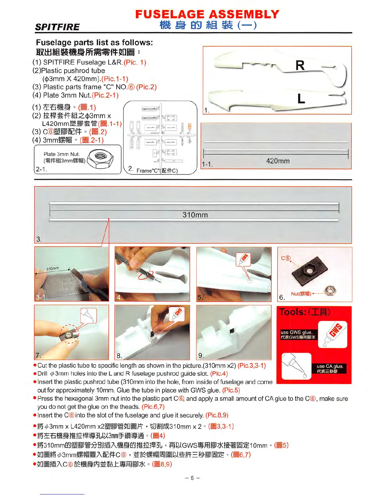
(1) SPITFIRE Fuselage L&R.(Pic. 1)
(2)Plastic pushrod
tube
(c|)3mm X
420mm).(Pic.
1-1)
(3) Plastic parts frame "C" NO.® (Pic.2)
(4) Plate 3mm Nut.(Pic.2-1)
°
(H.I)
^
(2) i4^^'f4^,®;^(})3mm x
L420mmMP#W(H.1-1)
(3)
cmmmi^
° (H.2)
(4)
3mm!lLl^i
° (H.2-1)
Plate
3mm
Nut.
(»ftili3mmtlli)
2-1.
Frame"C"(g-(4C)
1-1.
420mm
•J
310mm
3.
/
3lOmm
6
7
/.
/
1
•
Cut
the
plastic tube to specific length
as
shown in
the
picture.(310mm x2) (Pic.3,3-1)
•
Drill
03mm
holes into
the
L
and
R fuselage pushrod guide slot. (Pic.4)
• Insert the plastic pushrod tube (310mm intothe hole, from inside of fuselage
and
come
out
for approximately 10mm. Glue
the
tube in
place
with
GWS
glue. (Pic.5)
• Press the hexagonal 3mm nut intothe plastic part 0®, and apply a small amount of CAglue to the
C®,
make sure
you
do
not
get
the
glue on
the
theads.
(Pic.6,7)
• Insert the
C®
into the slot of the fuselage
and
glue itsecurely. (Pic.8,9)
•Hf
03mm
XL420mm
x2^P®5DHin
'
®iij]^310mm
x 2 °
(H3,3-1)
>
si^Gwssffi§i7j(jg^iii:£iomm
°
(bs)
03mm3i«BAieffC©
> °
me,7)
•mmmAcmmmp^mhJommmyK
°
(ms.g)
- 5 -
use
CA
giue