SPITFIRE
CAUTION:
(H^)
★
Before
assemble
the
fuselages,
check
which
version
of
power
system
(EPS-300C, EDP-400C
or
slope
Glider)you
purchase,
then
follow
according
to
that
version's
power
system
installation.
in7]s8igtii
°
EPS-300C
POWER
SYSTEM
INSTALLATION
VERSIONS
EPS-300C
• .
-•ffSIK
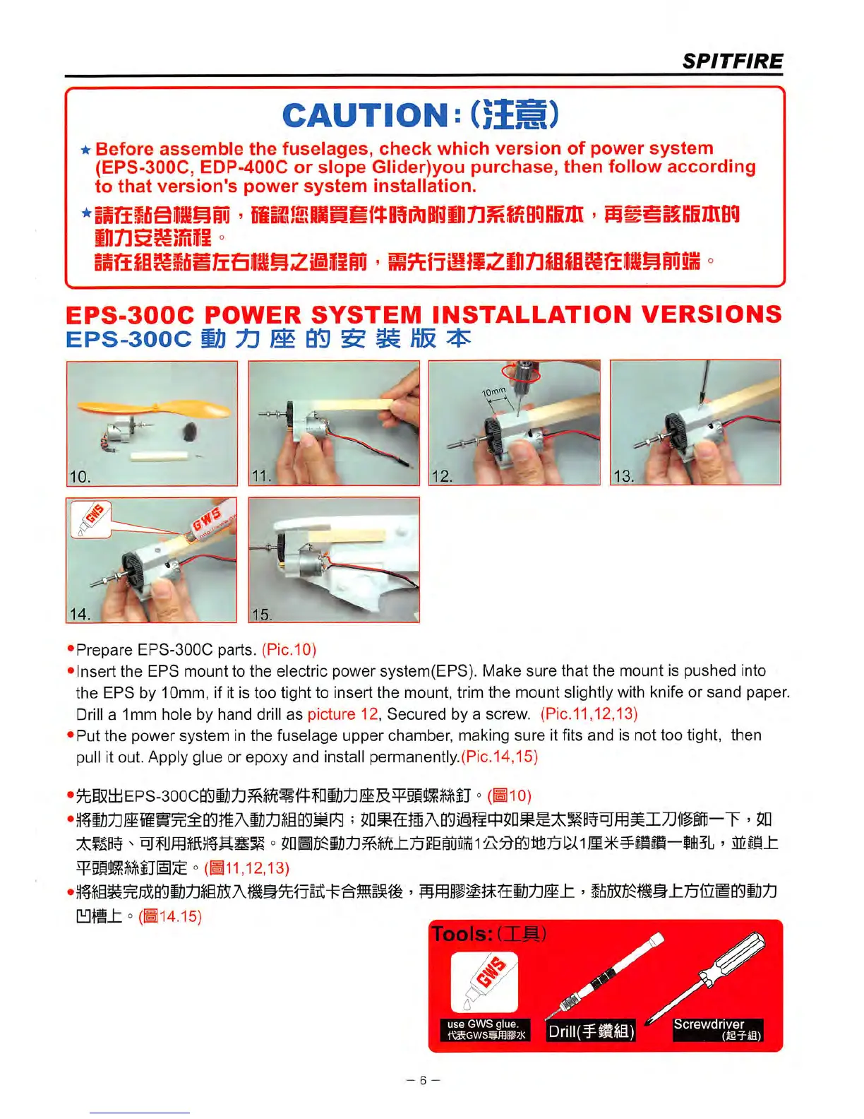
•Prepare
EPS-300C
parts.
(Pic.10)
•Insert
the
EPS
mount
to
the
electric
power
system(EPS).
Make
sure
that
the
mount
is
pushed
into
the
EPS
by 10mm, if it is too tight to insert
the
mount, trim
the
mount slightly with knife or
sand
paper.
Drill
a 1mm hole by
hand
drill
as
picture 12,
Secured
by a screw. (Pic.11,12,13)
•Put
the
power
system
in
the
fuselage
upper
chamber,
making
sure
it fits
and
is
not
too
tight,
then
pull it out. Apply glue or epoxy
and
install permanently.(Pic.14,15)
•^i5i±iEPs-3ooca^il];til^^i?c^1^ffiiJ;t]JlS^5lllMIJ
°
(Hio)
°
(Hi
1,12,13)
° (H14.15)
✓
^ use
GWS
glue.
|Drill(¥M)
Screwdriver
- 6 -