DT-1 - Spindle - Tool Clamp System - Push-Out Adjustment - Manual
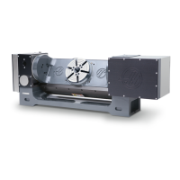
Tools Required
Also required: magnetic base, feeler gauges
1. Place the split tool in the spindle.
2. Indicate the ground surface of the split tool and zero the indicator.
3. Push up on the split tool to keep it from dropping and press Tool Release. The drawbar will push the
split tool out of the spindle.
4. Check the indicator. The tool should be pushed out 0.030". If the pushout varies from this value, adjust
the air cylinder clevis position in or out until the correct pushout is achieved.
NOTE: Each 180° rotation of the clevis adjusts pushout by approximately 0.010". If
an exact pushout of 0.030" cannot be achieved, adjust pushout to the closest
possible value over 0.030". For example, if pushout can only be adjusted to
0.025" or 0.035", adjust it to 0.035"
DT-1 - Spindle - Tool Clamp System - Push-Out Adjustment - Automatic
This adjusts tool push-out when tool release is controlled by the drawbar cam during tool changes.
1. Place the split tool in the spindle.
2. Set rapids to 5% and press ATC FWD to bring the spindle to tool change position. Press Emergency
Stop as soon as the spindle orients to tool change position and the carousel stops moving.
3. Indicate the ground face of the split tool and zero the indicator. Carefully move the indicator and base
away from the split tool (without disturbing the current indicator setting).
4. Make the tool changer axis visible (Parameter 462 bit 18), then jog it in the negative direction until the
split tool is fully released.
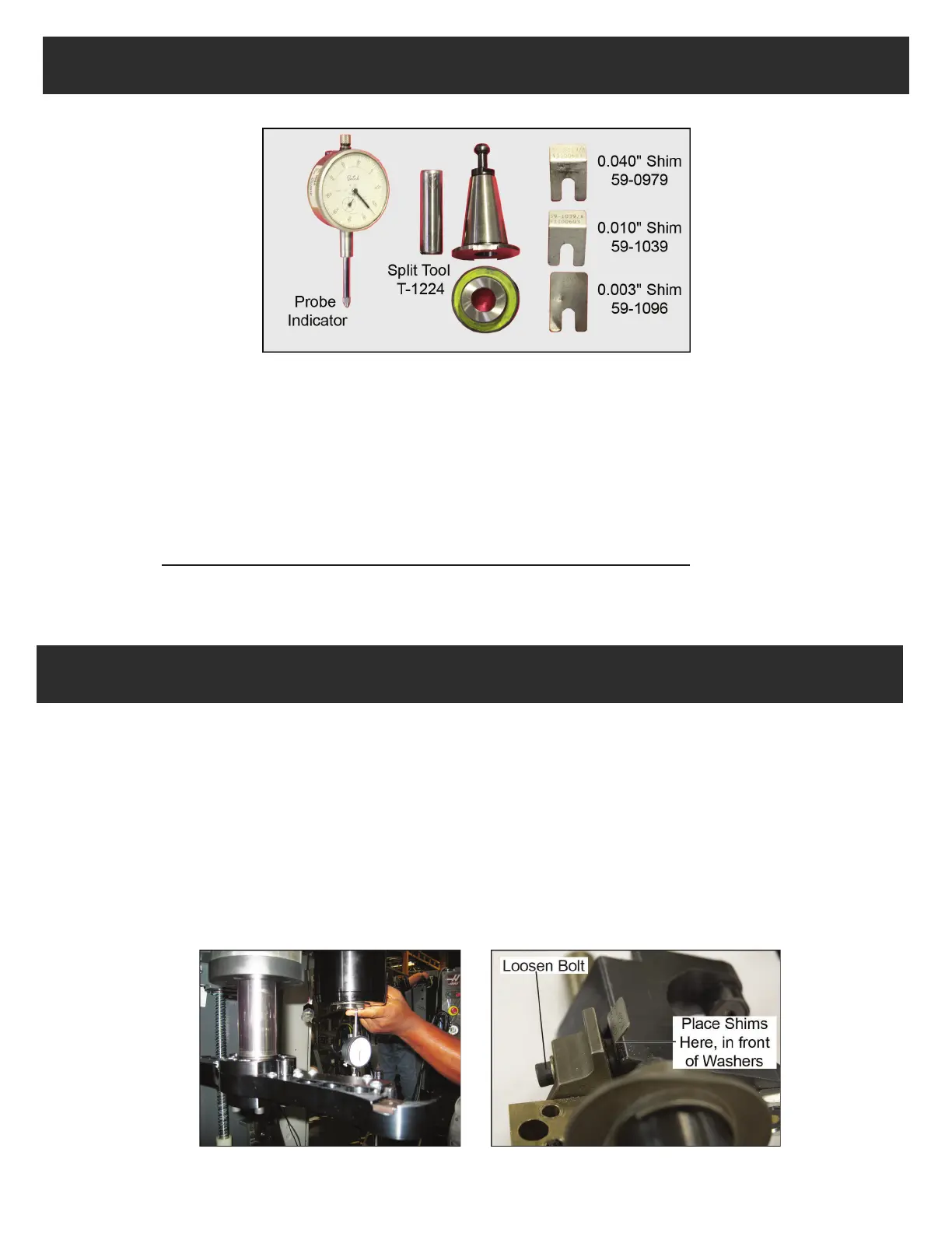
Measuring tool push-out Rocker Arm Shim Placement
© Copyright 2015 by Haas Automation, Inc. No unauthorized reproduction.
 Loading...