Do you have a question about the Haas TR160 and is the answer not in the manual?
Introduces the procedure for installing TR, TRT, or T5C rotary on a Haas VMC, defining A and B axes.
Warns to ensure correct voltage supply to the rotary before installation.
Emphasizes following basic safety precautions during maintenance to prevent injury and damage.
Advises that only qualified personnel should perform repairs; recommends HFO for service.
Warns that some service procedures are dangerous or life-threatening and advises contacting HFO if unsure.
States that initial rotary installation must be by a certified Haas Service Technician to avoid voiding warranty.
Machine must have a fourth and fifth axis drive installed for the rotary to operate.
Lists essential tools like lifting chains, spreader beam, lifting device, and dial indicator.
Specifies VMC compatibility and software version requirement for TRT100.
Details cable changes for CHC/NGC mills with trunnions made after Oct 2016 based on 4th axis scale.
Details cable changes for CHC/NGC mills with trunnions made before Oct 2016 based on 4th axis scale.
Prepare the machine by zero return, moving the table, and engaging the emergency stop.
Connect the rotary air hose to an air supply to engage the axis brake.
Ensure adequate air hose length to prevent damage to the rotary during installation.
Install eye bolts, lifting chains, and spreader beam for lifting the rotary.
Use spreader beam and chains correctly; ensure TILT Axis is flat to prevent rotary damage.
Install T-Nuts, pins, and then the rotary onto the machine table using a lifting device.
Install double-threaded studs, washers, and nuts for initial alignment adjustments.
Note that tilting the A Axis may be necessary to install all studs, washers, and nuts.
Remove standoffs and shipping brackets from specific locations on the rotary.
Reinstall screws in bracket locations to prevent coolant contamination; do not use platter screws.
Clean the machined surfaces of the rotary using a pH-neutral degreaser.
Disconnect air hose, remove shipping plate, and install the cable clamp on the enclosure.
Engage emergency stop, power off, set main breaker to OFF, and lock it with a safety tag.
Route the rotary air hose and cables into the machine enclosure and to the control cabinet.
Arrange cables neatly, label TILT (A Axis) and ROTARY (B Axis) cables, and zip-tie them.
Ensure cables have tension to hang properly without touching the table, then secure the cable clamp.
Remove dust covers and connect TILT and ROTARY axis cables to the control cabinet ports.
Connect the rotary scale cable to the SCALE A Axis port or coil it if no A-Axis Scales.
Set the main circuit breaker to ON and push POWER ON.
For NGC machines, perform the 'Enable and Disable' procedure and proceed to step 13.
Set PARAMETER 315 to enable FOURTH AXIS, and change setting 30 4TH AXIS ENABLE to NEW, selecting the correct rotary model.
If rotary model is unavailable, use USER1 for A-axis and consult a parameter list or HFO.
Change setting 78 5TH AXIS ENABLE to NEW, selecting the correct rotary model, or use USER2 for B-axis.
If B-axis model is unavailable, use USER2 and manually enter parameters using a list or HFO.
Power off, then power on the machine, and release the emergency stop.
Perform ZERO RETURN, check axis travel limits, and ensure cables are not pinched.
Tilt the A axis to gain access to the T-Nuts for final stud installation.
Install the remaining studs, washers, and nuts.
Adjust Parameter 212 to make the platter parallel to the Y-Axis movement using a dial indicator.
Check A-axis travel limits by jogging; ensure it stops at 120 degrees in each direction.
Align the multi-axis trunnion by tilting A-axis to 90 degrees and indicating platter parallelism to X-axis.
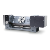
Lift rotary tables using lift rings and 1/2-13 eyebolts; air supply attachment is recommended before lifting.
Illustrates lifting configurations for various rotary models (TRT100, TR310, T5C-3, TR160, TR160Y, TR210) using spreader bars or eyebolts.
| Brand | Haas |
|---|---|
| Model | TR160 |
| Category | Industrial Equipment |
| Language | English |