This document provides comprehensive instructions for the installation of TR, TRT, and T5C rotary tables on Haas Vertical Machining Centers (VMCs). It covers the entire process from initial setup and safety precautions to electrical connections, parameter configuration, and final alignment. The trunnion axis is referred to as the A Axis (TILT), and the platter axis as the B Axis (ROTARY).
Function Description:
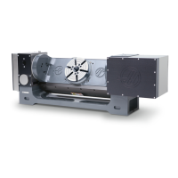
The Haas rotary tables (TR, TRT, and T5C models) are designed to add fourth and fifth axis capabilities to Haas VMCs, enabling complex multi-sided machining operations. These devices provide precise angular positioning and rotation for workpieces, significantly expanding the machining capabilities of the VMC. The installation guide details how to physically mount the rotary table onto the VMC's table, connect it to the machine's control system, configure the necessary software parameters, and perform critical alignment procedures to ensure accurate operation.
Important Technical Specifications:
While specific numerical technical specifications like weight, dimensions, or motor power are not explicitly listed within the provided text, the document highlights several important aspects related to the rotary tables:
- Axis Designation: The trunnion axis is consistently referred to as the A Axis (TILT), and the platter axis as the B Axis (ROTARY). This standardized nomenclature is crucial for understanding and configuring the machine's control system.
- Machine Compatibility: The rotary tables are compatible with "All VMCs" and specifically mention that for a TRT100, the machine must have software version M18.24A or higher. This indicates a requirement for specific software versions to support the rotary's functionality.
- Control System Integration: The installation involves connecting the rotary to the VMC's control cabinet, specifically to ports for A- and B-Axes. The document also addresses the need to connect a rotary scale cable for VMCs with A-Axis Scales, implying that some models may offer scale feedback for enhanced precision.
- Cable Configuration: Depending on the trunnion's manufacturing date (before or after October 2016) and the VMC's control type (Classic Haas Control - CHC or Next Generation Control - NGC), specific cable changes might be necessary. This includes removing or installing [+12V] or [+5VDC] ROTARY SCALE FEEDBACK CONTROL END cables (P/N 32-10065, 32-10053, 32-10049). This detail is critical for ensuring correct electrical communication and scale feedback.
- Alignment Precision: The alignment procedures emphasize achieving high precision. For horizontal adjustment (platter parallel to Y-Axis movement), the error must be less than 0.0003" (0.008mm). For alignment of the multi-axis trunnion (platter or collet face parallel to X-axis movement), the error also cannot exceed 0.0003" (0.008mm). These tight tolerances underscore the need for accurate installation to achieve desired machining results.
- Parameter Settings: The installation requires configuring specific parameters in the machine's control, including Setting 7 (PARAMETER to OFF), Parameter 315 (enable FOURTH AXIS and FIFTH AXIS), Setting 30 4TH AXIS ENABLE, and Setting 78 5TH AXIS ENABLE. The selection of the correct rotary model and axis (e.g., TR210-P4-TLT for A-axis, TR210-P4-ROT for B-axis) is crucial for the control to correctly interpret and operate the rotary.
- Lifting Hardware: The document specifies the use of 1/2-13 eyebolts for lifting all rotary tables (HRT's, TR's, TRT's, and T5C's). This standardized hardware simplifies the lifting process.
Usage Features:
The document primarily focuses on the installation process, which directly enables the usage of the rotary tables. Key usage-related features derived from the installation instructions include:
- Multi-Axis Machining: Once installed and configured, the rotary tables allow the VMC to perform 4th and 5th axis operations, enabling machining of complex geometries and multiple sides of a workpiece without re-fixturing.
- Precise Positioning: The alignment procedures ensure that the rotary table is accurately positioned relative to the machine's axes, allowing for precise angular indexing and contouring.
- Control Integration: The rotary tables are fully integrated with the Haas VMC's control system, allowing operators to program and control the A and B axes through standard G-code commands and machine settings.
- Brake System: The rotary tables incorporate a brake system that engages when air pressure is supplied. This is a safety and operational feature, preventing unintended movement and securing the axes during machining or setup.
- Parameter-Driven Configuration: The ability to select specific rotary models and axes via control parameters (e.g., Setting 30, Setting 78) simplifies the setup for different rotary units, allowing the machine to adapt its behavior to the installed hardware.
- Manual Adjustment for Alignment: The process of adjusting Parameter 212 for horizontal alignment and using a mallet for X-axis alignment demonstrates that fine-tuning is performed through a combination of software adjustments and physical manipulation, ensuring optimal performance.
Maintenance Features:
The document touches upon several aspects that relate to the maintenance and care of the rotary tables, primarily during installation:
- Safety Protocols: Emphasizes critical safety precautions such as setting the main circuit breaker to [OFF], using lock-out procedures, waiting for power to dissipate, turning off air supply, and resting the spindle head on a block of wood. These are fundamental for safe maintenance and installation.
- Professional Installation Requirement: States that "The initial installation of this rotary must be done by a certified Haas Service Technician. Initial installation by non-certified personnel invalidates the warranty of the rotary." This highlights the complexity and importance of correct installation for warranty validity and long-term reliability.
- Cleanliness: Instructs to "Make sure the machine table and the bottom of the rotary are clean" and to "Clean the machined surfaces of the rotary" using a pH-neutral degreaser. This prevents contamination and ensures proper seating and alignment.
- Hardware Retention: Advises to "Keep all of the hardware and the shipping brackets" after removal. This is important for potential future use, such as re-shipping or troubleshooting.
- Contamination Prevention: For the TR310, it instructs to reinstall screws in the same location after removing shipping brackets to "prevent contamination from coolant in the rotary unit." This is a specific design consideration to protect internal components.
- Cable Management: Instructions for routing and zip-tying cables, ensuring they "do not get caught on the table or get crushed" and "do not travel in a straight line from the hole to the rotary," are crucial for preventing cable damage and ensuring reliable operation, reducing future maintenance needs related to wiring.
- Air Hose Connection: The requirement to connect the rotary air hose to an air supply during lifting and installation is a protective measure, as it engages the brake to "prevent internal damage." This is a key maintenance-related operational step.
- Troubleshooting Guidance: The document provides guidance on what to do if issues arise, such as if the rotary model is not available in the control settings (select USER1/USER2 and manually enter parameters) or if the A-axis moves beyond 20 degrees past home (push [EMERGENCY STOP] and contact HFO). This indicates a structured approach to addressing potential problems during setup.