ES0205l 12-00
10
4. Turn the main circuit breaker to the ON position (rotate the shaft clockwise). Apply power to the
control by pressing the Power-On switch on the control panel. Verify that the Fault Indicator on
the 320V Power Supply (located above the main power transformer) displays the number 1,
which signifies a normal power-up sequence. Next, verify the DC bus voltage on pins 6 & 7 with
a voltmeter. The voltage should read approximately 335VDC if powered from 240V, or closer to
290V if powered from 208V. If the voltage is not at least 260VDC, call the Service Department.
This voltage will not be displayed on the diagnostic data page of the display.
5. Turn the main circuit breaker OFF by rotating its shaft counterclockwise. Close the door, lock
the latches, and turn the power back on.
ELECTRICAL OPERATION
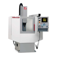
The Mini Mill operates the same as the other Haas Vertical Machining Centers, with the exception that the
spindle motor is driven by an amplifier on the Servo Drive assembly. A closed-loop Vector Drive function is
still performed, with the amplifier being controlled by the C-Axis output of the Mocon, as is the same for other
Haas machines. The amplifiers get their 320V power from a power supply specially designed to operate
efficiently from either Single Phase or 3 Phase power.
The 320V Power Supply limits the inrush current into the supply at power-on, and continuously monitors the
input voltage for a drop-out condition. It also provides the drive to the 15 Ohm Regen Load mounted on top
of the cabinet. It does this by sensing the voltage as the spindle motor decelerates and connecting the
Regen Load across the 320V output bus to absorb the excess motor energy.
Fault Display
The 320V Power Supply has a Fault Display that displays different faults sensed by the power supply. Any
of the faults will cause the power supply to disable the DC bus. The Fault Display will continue to be illumi-
nated with the fault code until the power to the control cabinet has been turned-off. This is the only way of
resetting the power supply.
Fault Code Description Diagnosis
4 Over-Temp Fan Failed
A Phase A/C Frequency not 49-61Hz, loss of AC for 3 cycles
b Regen Regen Load is shorted
d Overload/Short Excessive current on DC output - shorted amp
E Under Voltage AC Input voltage is low
F Over Voltage Regen Load is open
In addition, the supply cycles through the codes 8, 0, and 1 during the power-up sequence. 8 is
displayed when power is first applied to allow verification that all segments of the display are working prop-
erly. 0 is next displayed to indicate that the supply has begun charging the output capacitors. This takes
approximately 5 seconds. 1 is next displayed to indicate that the capacitors were successfully charged.
Unless a fault occurs, the 1 code remains displayed while AC power is applied.

 Loading...