7796-8000
June 1999
OPERATION
Keep in mind that the zero position may be placed at any point along each of the three number lines, and in
fact will probably be different for each setup of the machine. It is noteworthy to mention here that the Z-axis is
usually set with the machine zero position in the full upward position, or the tool change position. This will
place all the Z moves in a negative range of travel. However, the work zero in the Z-axis is usually set at the top
of the part surface, and this will be entered in the tool length offset as a negative value. The range of travel on
the HAAS VF-1, for example, is a total of 20 inches; four of these inches are above tool change position and
are listed as a positive tool length offset, and 16 of these inches are below tool change position and are listed
as a negative tool length offset.
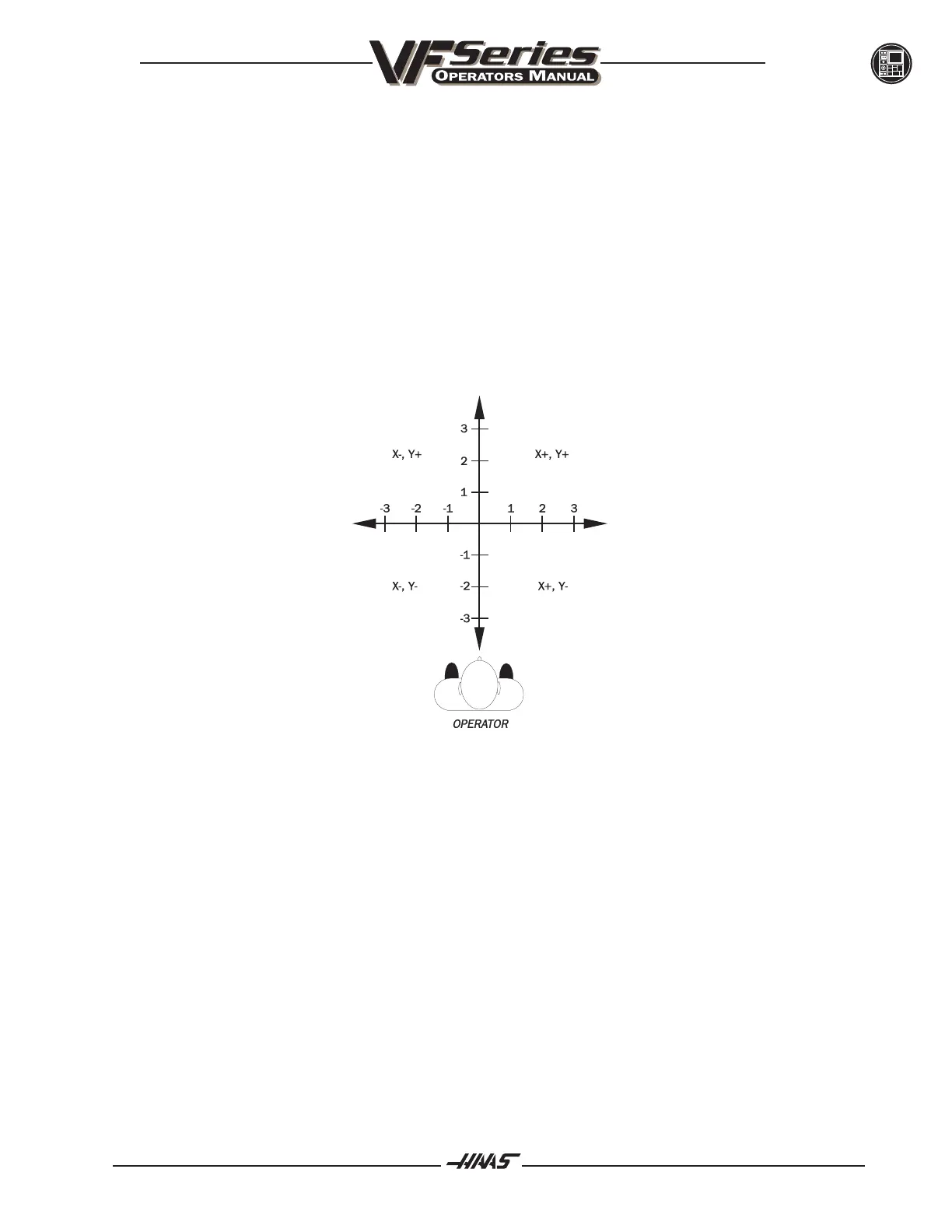
The diagram shows a top view of the grid as it would appear on the machine tool. This view shows the X and Y
axes as the operator faces the machine tool. Note that at the intersection of the two lines, a common zero
point is established. The four areas to the sides and above and below the lines are called QUADRANTS and
make up the basis for what is known as rectangular coordinate programming.
Fig. 3-4 View of X,Y grid from above.
THE TOP LEFT QUADRANT IS= X-.Y+
THE BOTTOM LEFT QUADRANT IS= X-,Y-
THE TOP RIGHT QUADRANT IS= X+,Y+
THE BOTTOM RIGHT QUADRANT IS= X+,Y-
Whenever we set a zero somewhere on the X-axis and somewhere on the Y-axis, we have automatically
caused an intersection of the two lines. This intersection where the two zeros come together will automatically
have the four quadrants to its sides, above, and below it. How much of a quadrant we will be able to access is
determined by where we placed the zero within the travel of the machine axis.
For example, for a VF-1, if we set zero exactly in the middle of the travel of X and Y (table center), we have
created four quadrants that are 10 inches by 8 inches in size.