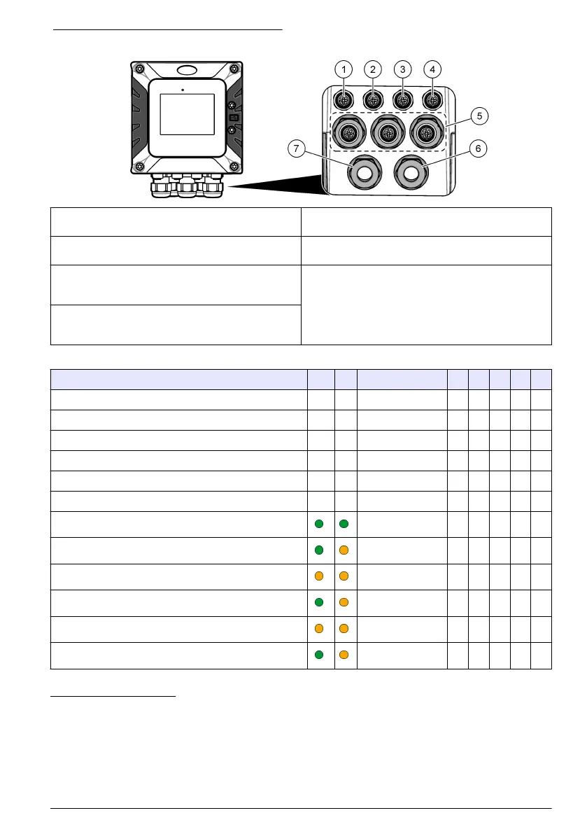
Figure 6 Electrical connectors and fittings
1 Ethernet connector (optional) for LAN port 1 or
EtherNet/IP or PROFINET connector
5 Strain relief fitting for USB box and expansion
modules: Analog inputs/outputs, Profibus DP
2 Ethernet connector (optional) for LAN port 2 or
EtherNet/IP or PROFINET connector
6 Power cord (or conduit hub)
10
3 Digital SC connector: Channel 1. Optional: Analog
sensor connection to sensor module or analog input
connection to 4-20 mA input module
9
7 Strain relief fitting for high voltage relay
4 Digital SC connector: Channel 2. Optional: Analog
sensor connection to sensor module or analog input
connection to 4-20 mA input module
Table 1 Options for each connector and fitting
Device 1
11
2 Option
12
3 4 5 6 7
sc digital sensor, sc digital gateway or analyzer X X
Analog sensor X X
4-20 mA input X X
4-40 mA output X
Profibus DP module X
USB Box X
LAN + LAN Split / Chaining
LAN + Modbus TCP Mix IEP
EtherNet/IP IEP only
LAN + EtherNet/IP Mix IEP
PROFINET IEP only
LAN + PROFINET Mix IEP
9
To connect an analog sensor or 4-20 mA input to the controller, install the applicable expansion
module, if not already installed. Refer to the documentation supplied with the expansion module
for additional information.
10
The power cord is factory-installed based on the controller configuration.
11
A color code identifies the connectors. The LAN connectors are green. The EtherNet/IP or
PROFINET connectors are yellow.
12
Refer to LAN connection on page 25 for Ethernet port configuration options.
English 13