Chapter 3, Basic Care and Preventive Maintenance 3-3
Filter Inspection
Inspect for the following filters. Refer to the repair parts list in Chapter 7
for correct part numbers to replace if worn.
• The three air filters on the bottom of the machine.
• The two cuff compressor filters on the front panel.
The components in the PCS2 generate enough heat that some circuits may
drift if the cooling system is not intact. For this reason, the rear panel
should always be propped into place whenever direct access through the
rear opening is not necessary. The cooling system is even more efficient
when both panels are in place, but it may be impractical to repeatedly
remove and replace the front panel. If a voltage measurement is needed,
be sure the internal temperature has stabilized before testing.
P
ower Supply V
oltages T
est
1. Power on the PCS2 in the Utilities mode of operation by pressing and
holding the PLASMA key while switching the power on. Hold the
PLASMA key until the Utilities menu appears on the display.
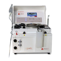
2. Measure the power supply voltages at P507 on the backplane card.
Use pin seven for DC common/ground. Note: Pins 1 thru 7 are all
common/ground.
PIN # Voltage Tolerance
8 +5.1 +0.1 / -0
9 +5.1 +0.1 / -0
10 +15.0 ±0.5
11 –15.0 ±0.5
12 +28.0 +1.0 / – 0.2
13 +28.0 +1.0 / – 0.2
14 +48.0 +47 to +57
Figure 3-1, Backplane Card
Consumables
Replacement
Calibration
Testing