Excel-EN Installation, Commissioning & Operating Manual Approved Document Ref: UI-XLEN-01 Issue 7.0
24
SETUP & PROGRAMMING
1 1 1 1
View History
The control panel stores a log of the last 40 events which have occurred. This is useful for identifying
intermittent faults or activations.
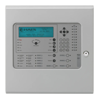
Enter the above code and press ENTER, the most recent event that has
occurred is displayed. Use the ENTER button to progress backwards
through the indications.
When the end of the log is reached the panel will drop out of view mode.
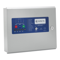
During viewing it is possible to delete the entire history by pressing and
holding button 2. The panel will chirp to acknowledge deletion.
The panel will log and display the following events: zone fi re activations, zone faults, power supply faults,
sounder circuit faults and repeater faults.
The last two (sounder circuit faults and repeater faults) have additional
information available which can be accessed by pressing and holding the
ENTER button continuously.
Sounder circuit faults
If a sounder circuit fault is displayed, pressing and holding the ENTER button will reveal which sounder
circuit was at fault. This is indicated by the fi re LEDs 1 - 6 as per the table below.
Repeater faults
If a repeater fault is displayed, pressing and holding the ENTER button will reveal the following further
information.
The Repeater Fault LED indicates:
Slow Flash = faulty repeater, Normal Flash = repeater off line, Fast Flash = network cable error.
Red, fi re LEDs 1 - 8 indicate which repeater was off line
Amber, fault LEDs 1 - 8 indicate which repeater had a PSU fault
Zone 1 fi re LED Zone 2 fi re LED Zone 3 fi re LED Zone 4 fi re LED Zone 5 fi re LED Zone 6 fi re LED
Main PCB
SNDR 1
Main PCB
SNDR 2
Zone extension
card 1 (zones 5
- 8) SNDR A
Zone extension
card 1 (zones 5
- 8) SNDR B
Zone extension
card 2 (zones 9
- 12) SNDR A
Zone extension
card 2 (zones 9
- 12) SNDR B
RESOUND SILENCE RESET
ENTER
1234
Disable
Mode
Test
Mode
Mute
Buzzer
Test
Lamps
RESOUND SILENCE RESET
ENTER
1234
Disable
Mode
Test
Mode
Mute
Buzzer
Test
Lamps
RESOUND SILENCE RESET
ENTER
1234
Disable
Mode
Test
Mode
Mute
Buzzer
Test
Lamps
When fi nished, enter the next programming code or disable the controls and return DIL switch 6 to ‘OFF’.