Excel-EN Installation, Commissioning & Operating Manual Approved Document Ref: UI-XLEN-01 Issue 7.0
29
SETUP & PROGRAMMING
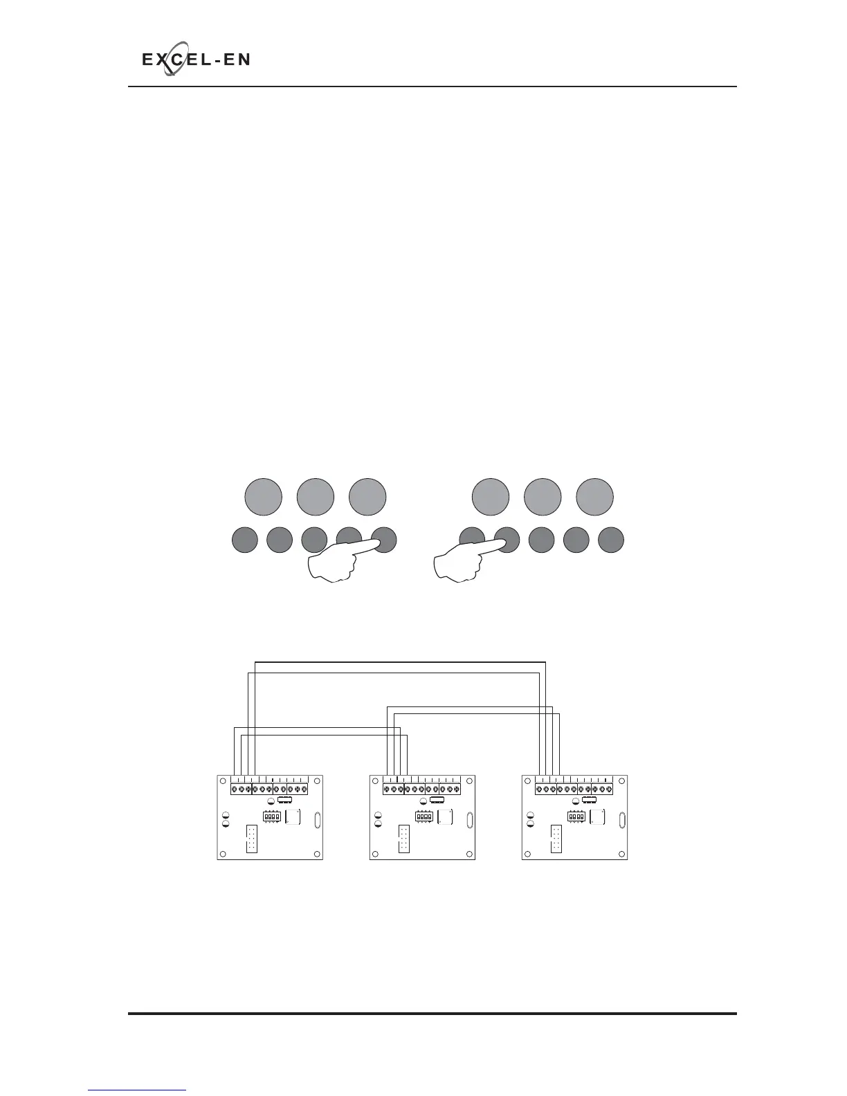
OPTION 6. Change Network/Repeater Comms Monitoring Type (EN54!)
The network & repeater panels are designed to be wired in a fault tolerant (fail safe) loop confi guration,
from comms A to B and back to the main panel again (see drawing below). This enables network &
repeater panels to still work if there is a break in the cables.
If replacing an older system where the existing cabling cannot be confi gured in a loop as above, it is
possible to change the panel back to radial circuit comms monitoring.
With the zone 6 fi re LED lit, the amber, fault LED will show the current setting.
LED 1 OFF = fault tolerant monitoring (default). LED 1 ON = legacy, radial circuit monitoring.
Press the ENTER button, zone 6 fi re LED will pulse to indicate ‘edit mode’.
Now use button 2 to change the setting indicated by the amber fault LED ON or OFF as per above.
When fi nished press the ENTER button again and the zone 6 fi re LED will return to steady ‘view mode’.
Press button 1 to move to next option or hold button 1 for 3 seconds to exit programming mode 2-1-2-3.
RESOUND SILENCE RESET
ENTER
1234
Disable
Mode
Test
Mode
Mute
Buzzer
Test
Lamps
RESOUND SILENCE RESET
ENTER
1234
Disable
Mode
Test
Mode
Mute
Buzzer
Test
Lamps
COMS A COMS B 28
V+
SW -ve OUTPUTS
+-
+-
12345 6
1 2 34
ON
ADDRESS
COMS A COMS B 28
V+
SW -ve OUTPUTS
+-
+-
12345 6
1 2 34
ON
ADDRESS
COMS A COMS B 28
V+
SW -ve OUTPUTS
+-
+-
12345 6
1 2 34
ON
ADDRESS
Fault Tolerant Loop Wiring
Main Panel Repeater/Network Panel 1 Repeater/Network Panel 2