Excel-EN Installation, Commissioning & Operating Manual Approved Document Ref: UI-XLEN-01 Issue 7.0
35
SETUP & PROGRAMMING
ZONE B - Set to Fire Pump Indication
The second zone will confi rm that the pump has started to run due to demand for fi re extinuishing water:
Pump idle;
• i.e. 4K7 EOL resistor only. No indication at all (normal)
Pump running;
• 3K9, Zone fi re LED comes on and panel buzzer sounds intermittently, the general fi re alarm and
alarm bells do NOT operate and the alarm is non latching.
Pump fail to run;
• 470 Ohm, Zone fault LED on and panel buzzer sounds continuously but with the general fi re and
sounder circuits inhibited and the alarm / fault conditions are no latching.
Select zone(s) to be programmed for Gate Valve or Fire Pump status monitoring as per ‘Zone Function
Settings’ programming mode 3-1-2-1.
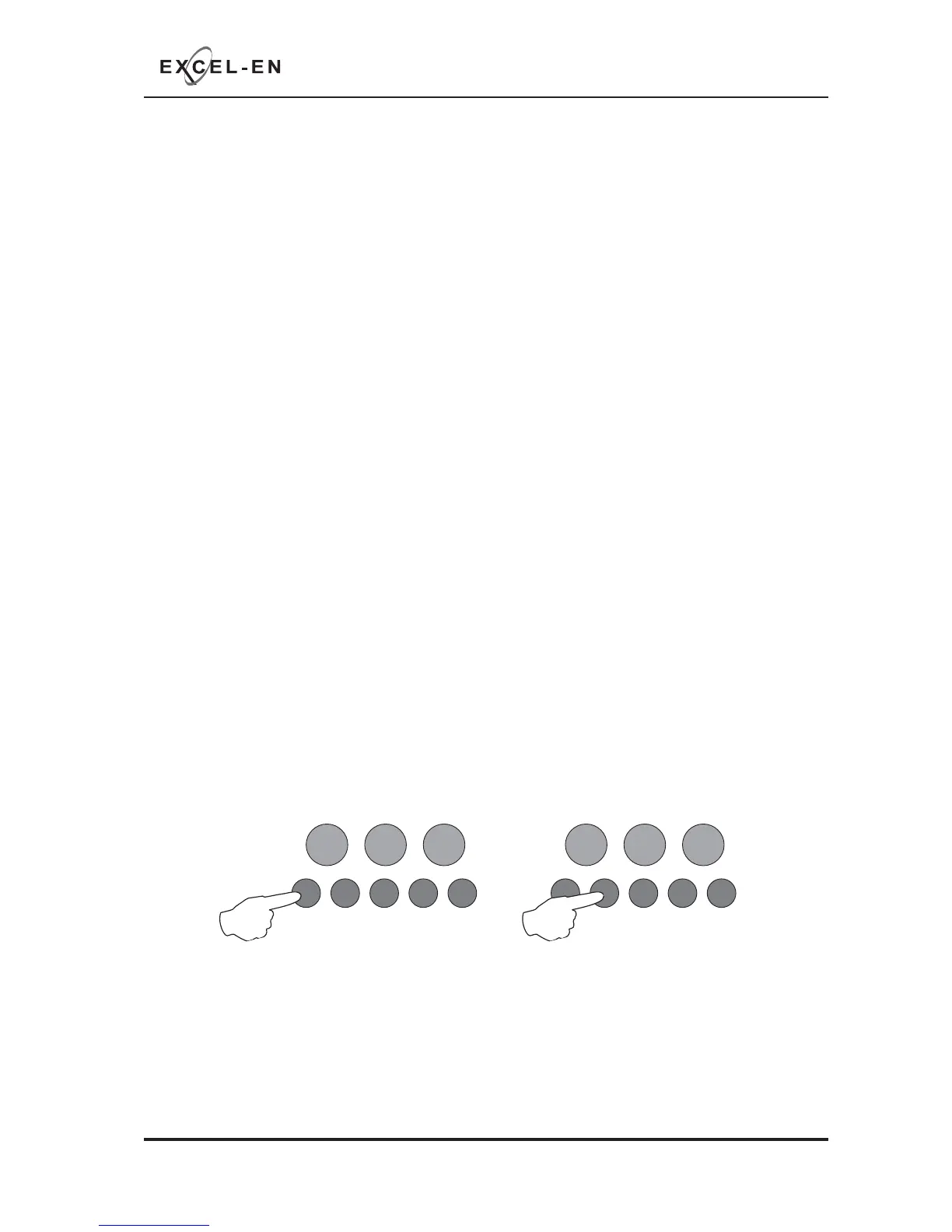
With the required zone for editing LED lit, press the ENTER button to enter ‘editing mode’.
The fi re zone 1 LED will now pulse to indicate the editing of attribute 1 (fi re latching) for the selected zone.
Use button 1 to scroll to pulsing fi re LED 8 (gate valve & fi re pump indications).
Then use button 2 to set the status required for that zone, indicated by the amber, fault LED.
OFF = normal zone
ON = Gate Valve Status Indication
PULSING = Fire Pump Status Monitoring
RESOUND SILENCE RESET
ENTER
1234
Disable
Mode
Test
Mode
Mute
Buzzer
Test
Lamps
RESOUND SILENCE RESET
ENTER
1234
Disable
Mode
Test
Mode
Mute
Buzzer
Test
Lamps
When fi nished all the zone function programming, enter the next programming code or disable the controls
and return DIL switch 2 to ‘OFF’.
Press the ENTER button to return back to the zone selection, indicated by a steady zone fi re LED