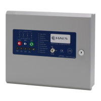
Excel-EN Installation, Commissioning & Operating Manual Approved Document Ref: UI-XLEN-01 Issue 7.0
49
SETUP & PROGRAMMING
4
3
3
2
2
2
4
4
Sounder Circuit Network Responses
Twin Wire Sounder Circuit Network Responses
The six possible sounder circuits in the panel will, by default, activate continuously for any fi re condition
from the entire network.
This option enables the default to be changed for each of the local circuits. The response can be either;
CONTINUOUS, PULSING or NONE when a fi re condition is received
from any other panel in the network.
Enter the above code and press the ENTER button.
The zone 1 fi re LED will pulse indicating setting the response for sounder
circuit 1.
Sounder circuits 1 - 6 are represented by zone LEDs 1 - 6 respectively.
A pulsing red fi re LED indicates which circuit is selected and the setting is represented by the amber fault
LED as per table below.
Use button 1 to move the pulsing fi re LED to the required circuit, then use button 2 to change the response
of the circuit, indicated by the amber fault LED. Each press of button 2 will toggle through the 3 available
responses.
If using Twin Wire zones, the sounders connected to each of the Twin Wire circuits will, by default, activate
continuously for any fi re condition from the entire network.
This option enables the default to be changed for each of the local Twin Wire sounder circuits. The response
can be either; CONTINUOUS, PULSING or NONE when a fi re condition is received from any other panel
in the network.
The process is exactly as descibed above but using code 3-2-2-4.
Use button 1 to select the Twin Wire sounder circuit, represented by zone LEDs 1 - 12 respectively. A
pulsing red fi re LED indicates which circuit is selected and the setting is represented by the amber fault
LED. Then use button 2 to edit the response as per table above.
Amber LED ON Sounder circuit activates CONTINUOUSLY for other network panel fi res
Amber LED PULSING Sounder circuit PULSES for other network panel fi res
Amber LED OFF Sounder circuit NO RESPONSE for other network panel fi res
RESOUND SILENCE RESET
ENTER
1234
Disable
Mode
Test
Mode
Mute
Buzzer
Test
Lamps
When fi nished, press and hold Button 1 for 3 seconds to save setting and exit programming mode.
Note:- The sounder circuit & Twin Wire sounder circuit responses to a fi re condition from their own panel
are set using programming options 4-3-4-2 & 3-1-2-2.
If a local response has been programmed, consideration should also be given to the network response
which may affect it.
LED 1 LED 2 LED 3 LED 4 LED 5 LED 6
SNDR1
(Main
PCB)
SNDR2
(Main
PCB)
SNDR A.
Zone ext card
1 (Zones 5
- 8)
SNDR B.
Zone ext card
1 (Zones 5
- 8)
SNDR A.
Zone ext card
2 (Zones 9 -
12)
SNDR B.
Zone ext card
2 (Zones 9 -
12)



 To Next Page