Mortise Lock Exit Device
Installation Instructions
I-ED01553
Rev 4, Rev Date: 06/19/18 27390043 Page 4 of 10
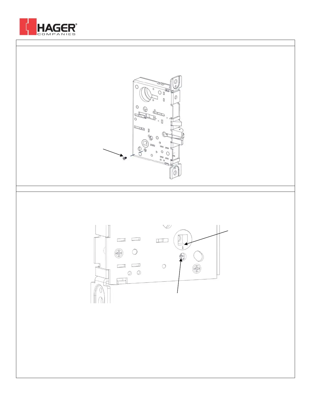
4. SET OUTSIDE HANDING OF LOCK CASE (BE AND CE FUNCTIONS ONLY)
Skip this step for NL and DT functions. There is a catch screw on each side of the lock body. For BE and CE functions a catch screw
must be removed on the PULL side of the lock body. The catch screw must stay in the PUSH side of the lock body.
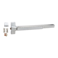
5. SET HUB (BE AND CE FUNCTIONS ONLY)
Check the hub of the lock case to make sure the arrow is pointing downwards toward the hole underneath it. If it is not in this
position adjust it by rotating the hub until the arrow points down. This can be done by inserting the handing pin in the hub and
turning it with a pair of pliers.