EasyManua.ls Logo

hager 4501 - User Manual

hager 4501
3 pages
Print Icon
To Next Page IconTo Next Page
Loading...
4500/4600 Series Electric Exit Device
Installation Instructions
I-ED00367
Rev 8, Rev Date: 8/27/2018 27390025 Page 1 of 3
Hager Companies 139 Victor Street, St. Louis, MO 63104 (800) 325-9995 www.hagerco.com
ELECTRICAL SPECIFICATIONS AND COLOR CODES FOR WIRES
For use with all Hager monitored exit device modifications.
Request to Exit (RX) switch monitors egress by push bar activation of the exit device.
Latch Bolt Monitoring (LM) switch monitors the latch mechanism of the exit device.
Authorized Ingress (AI) switch monitors ingress by trim or key retraction of the exit device latch.
Request to Exit (RX)
Latch Bolt Monitoring (LM)
Authorized Ingress (AI)
Electrical
Specification
SPDT Monitoring Switch
Maximum Contact Rating:
3 AMP @125VAC
2 AMP @ 30VDC
SPDT Monitoring Switch
Maximum Contact Rating:
3 AMP @125VAC
2 AMP @ 30VDC
SPDT Monitoring Switch
Maximum Contact Rating:
3 AMP @125VAC
2 AMP @ 30VDC
Color Code
for wires
Yellow Wire Common
Red Wire Normally Open
Grey Wire Normally Closed
Wire Gauge #22 AWG
Black Wire Common
White Wire Normally Open
Red Wire Normally Closed
Wire Gauge #22 AWG
Black Wire Common
Orange Wire Normally Open
Purple Wire Normally Closed
Wire Gauge #22 AWG
WIRE ROUTING AND DOOR PREP INSTRUCTIONS
1. Follow exit device instructions and template to prepare door and frame for installation.
2. Door fabricator to provide a 3/8” ** diameter (minimum) raceway through door to allow insertion of
electrical wires running between exit device and power transfer device (electric hinge).
Door fabricator to provide a
3/8” ** diameter (minimum)
Raceway through door to
Allow insertion of electrical
Wires running between exit
Device and power transfer
device
**
DEVICES COVERED IN THIS DOCUMENT:
LM Latch Bolt Monitoring * DE Delayed Egress
ELR Electric Latch Retraction (not for use with Mortise Exit)* AI Authorized Ingress *
RX Request to Exit (Field Installation Kit 2-649-5001) * RX2 Dual Request to Exit
ED Electric Dogging * ET Electric Trim (4500 Series only)
EL or EU Electrified Mortise Trim (ordered with 4501N Exit) * OBDE-On-Board Delayed Egress
MLR Motorized Latch Retraction (Field Installation Kit 2-649-5007) *
* Quick Connects Optional
** Quick Connects Require 5/8” Raceway

Other manuals for hager 4501

Question and Answer IconNeed help?

Do you have a question about the hager 4501 and is the answer not in the manual?

Summary

ELECTRICAL SPECIFICATIONS AND COLOR CODES FOR WIRES

Request to Exit (RX)

Details electrical specs and wire color codes for the Request to Exit (RX) monitoring switch.

Latch Bolt Monitoring (LM)

Details electrical specs and wire color codes for the Latch Bolt Monitoring (LM) switch.

Authorized Ingress (AI)

Details electrical specs and wire color codes for the Authorized Ingress (AI) monitoring switch.

WIRE ROUTING AND DOOR PREP INSTRUCTIONS

QUICK CONNECTS

Quick Connect Harness Cable Pinning

Details pin assignments and wire colors for the Hager Quick Connect Harness Cable.

4501;4601 Quick Connect Pinning

Details pin assignments and wire colors for the 4501/4601 series Quick Connects.

Overview

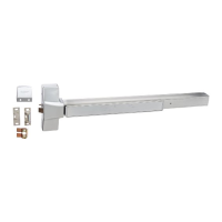
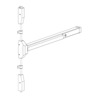
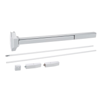
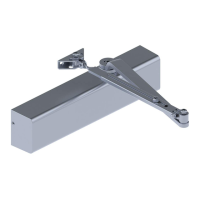
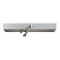
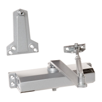
This document provides installation instructions for the Hager 4500/4600 Series Electric Exit Device, identified by document number I-ED00367. It covers various electrified modifications and their associated wiring specifications.

Function Description

The Hager 4500/4600 Series Electric Exit Device offers a range of electrified functions designed to enhance security, access control, and monitoring capabilities for doors. These functions include:

  • LM - Latch Bolt Monitoring: This feature monitors the state of the latch bolt, indicating whether it is extended or retracted. It uses a SPDT (Single-Pole, Double-Throw) monitoring switch.
  • ELR - Electric Latch Retraction: This function allows for remote retraction of the latch bolt, typically for controlled access or automatic door operation. It is not compatible with Mortise Exit devices.
  • RX - Request to Exit: This modification detects when the push bar of the exit device is activated, signaling an attempt to exit. It uses a SPDT monitoring switch. A field installation kit (2-649-5001) is available for this function.
  • ED - Electric Dogging: This feature allows the exit device's latch bolt to be held in a retracted (dogged) position electrically, enabling free passage without operating the push bar.
  • EL or EU - Electrified Mortise Trim: These options are for electrified trim used with 4501N Mortise Exit devices. They are specifically for the Night Latch Version (4501N) and are ordered with the device but are part of the Mortise Exit Lock Body.
  • MLR - Motorized Latch Retraction: Similar to ELR, this function provides motorized retraction of the latch bolt. A field installation kit (2-649-5007) is available.
  • DE - Delayed Egress: This function introduces a time delay before the exit device allows egress, typically used in applications where controlled exit is required for security or safety.
  • AI - Authorized Ingress: This feature monitors when authorized ingress occurs, such as through trim or key retraction of the exit device latch. It uses a SPDT monitoring switch.
  • RX2 - Dual Request to Exit: This is a variation of the Request to Exit function, likely offering redundant or additional exit request signaling.
  • ET - Electric Trim: This refers to electrified trim options specifically for 4500 Series devices.
  • OBDE - On-Board Delayed Egress: This indicates a delayed egress function where the control logic is integrated directly into the device.

Important Technical Specifications

The electrical specifications for the monitoring switches are consistent across LM, RX, and AI functions:

  • Switch Type: SPDT Monitoring Switch
  • Maximum Contact Rating:
    • 3 AMP @ 125VAC (Volts Alternating Current)
    • 2 AMP @ 30VDC (Volts Direct Current)

Wire Color Codes for Monitoring Switches:

  • Request to Exit (RX):
    • Yellow Wire: Common
    • Red Wire: Normally Open
    • Grey Wire: Normally Closed
    • Wire Gauge: #22 AWG
  • Latch Bolt Monitoring (LM):
    • Black Wire: Common
    • White Wire: Normally Open
    • Red Wire: Normally Closed
    • Wire Gauge: #22 AWG
  • Authorized Ingress (AI):
    • Black Wire: Common
    • Orange Wire: Normally Open
    • Purple Wire: Normally Closed
    • Wire Gauge: #22 AWG

Usage Features

  • Monitoring Capabilities: The RX, LM, and AI switches provide crucial feedback on door status, enabling integration with access control systems, security alarms, and building management systems.
  • Electrified Control: ELR, MLR, ED, DE, and ET functions allow for remote control of the exit device, enhancing operational flexibility and security.
  • Compatibility: The document emphasizes the need to follow specific exit device instructions and templates for proper installation, ensuring compatibility with the door and frame.
  • Door Preparation: A minimum 3/8" diameter raceway through the door is required for electrical wires running between the exit device and the power transfer device (electric hinge). For Quick Connects, a 5/8" raceway is necessary. A reinforcement plate is recommended for device mounting.
  • Wire Entry Hole Location: The exact location of the wire entry hole on the door depends on the backset and specific door application. Users must refer to the individual 4500/4600 Series Installation template for appropriate dimensions.
  • Device Length Modification: Standard 3-foot exit devices with ELR and Electric Dogging cannot be cut from the factory length. Standard 3-foot exit devices with MLR can be cut a maximum of two inches.
  • End Cap and Wire Routing: Instructions are provided for mounting the exit device end cap and routing wires to the power transfer device.
  • Function Exclusivity: The ELR, MLR, DE, and ED functions all occupy the same space in the push bar. Therefore, they cannot be used in conjunction with each other, cylinder dogging, or any Alarm Kit functions.
  • Quick Connects (Optional): Quick connects are available for the wires from the exit device electrification options. These are compatible with Hager Quick Connect Harness Cables, which can be used to plug into Hager hinges with quick connects for simplified and accurate wiring.

Quick Connect Pinning Details:

The document provides detailed pinning for both 8-pin and 4-pin Quick Connect Harness Cables and Terminals.

8-Pin Quick Connect Harness Cable Pinning:

  • Pin #1: Black
  • Pin #2: Red
  • Pin #3: White
  • Pin #4: Green
  • Pin #5: Orange
  • Pin #6: Blue
  • Pin #7: Brown
  • Pin #8: Yellow

4-Pin Quick Connect Harness Cable Pinning:

  • Pin #1: Violet
  • Pin #2: Gray
  • Pin #3: Pink
  • Pin #4: Tan

4501/4601 Quick Connect Pinning (Hager Exit Quick Connect Terminals):

8-Pin Terminal:

  • Pin #1: Power* (Color*) - *Black (ED)
  • Pin #2: Power* (Color*) - *White (MLR)
  • Pin #3: RX (Com) - Yellow
  • Pin #4: RX (N/O) - Red
  • Pin #5: RX (N/C) - Gray
  • Pin #6: AI (Com) - Black
  • Pin #7: AI (N/O) - Orange
  • Pin #8: AI (N/C) - Purple

4-Pin Terminal:

  • Pin #1: Blank - Blank
  • Pin #2: LM (Com) - Black
  • Pin #3: LM (N/O) - White
  • Pin #4: LM (N/C) - Red

Maintenance Features

The document primarily focuses on installation and initial setup. While it doesn't explicitly detail maintenance features, the clear wiring diagrams and specifications for quick connects suggest an design intended to simplify troubleshooting and potential component replacement. The use of standard wire gauges and clearly defined color codes would aid in any future diagnostic or repair work. The modular nature implied by quick connects also suggests easier field servicing.

hager 4501 Specifications

General IconGeneral
Brandhager
Model4501
CategoryDoor Opening System
LanguageEnglish

Related product manuals