EasyManua.ls Logo

hager 4500 Series - User Manual

hager 4500 Series
11 pages
Print Icon
To Next Page IconTo Next Page
Loading...
4500 Series Surface Vertical Rod Exit Device
Installation Instructions
Grade 1
I-ED00792
DEVICES COVERED IN THIS DOCUMENT:
4500S Surface Vertical Rod Device 4500S Less Bottom Rod (LBR) Device
4500SF Fire Exit Surface Vertical Rod Device 4500SF Fire Less Bottom Rod (LBR) Device
REV 3 Page 1 of 11
APPLICATIONS
Double Door Double Door with Rim Device
Metal Wood Wood and Metal
Screws
TOOLS REQUIRED
#7
1/4” - 20
1/8”
Machine Screws
#7 drill, 1/4” - 20 tap
For wood doors, drill
1/8” hole
Sex Bolts
Drill 5/16” thru from device
side. Drill 3/8” from other
side (pull side).
Check building and fire
codes to see if your
application requires the use
of sleeve nuts and bolts.
26490169

Other manuals for hager 4500 Series

Question and Answer IconNeed help?

Do you have a question about the hager 4500 Series and is the answer not in the manual?

Summary

APPLICATIONS

Double Door

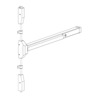
Illustrates the application of the vertical rod exit device on a double door setup.

Double Door with Rim Device

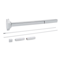
Shows how the vertical rod exit device is used with a rim device on a double door.

EXIT DEVICE PARTS AND SUB-ASSEMBLIES

LBR DEVICE NOTES

1. CUT EXIT DEVICE TO LENGTH

2. MARK DOOR AND DRILL MOUNTING HOLES

3. INSTALL EXIT DEVICE

4. INSTALL END CAP

5. INSTALL BOTTOM LATCH MOUNTING BRACKET

6. INSTALL BOTTOM STRIKE

7. INSTALL BOTTOM LATCH AND ROD

8. INSTALL TOP MOUNTING BRACKET

9. INSTALL TOP LATCH AND STRIKE

10. INSTALL TOP ROD

11. ADJUST AND TEST INSTALLATION

12. INSTALL COVERS

Install Head Cover Plug (FOR LBR DEVICES ONLY)

Describes installing a plug for LBR devices to block an unused hole in the head cover.

13. INSTALL ROD GUIDES

14. DOG DEVICE

Hex Wrench Dogging

Explains how to engage and disengage the dogging feature using a hex wrench.

Cylinder Dogging

Details the process of installing and using a mortise cylinder for dogging the exit device.

15. INSTALL AUXILIARY FIRE LATCH

Overview

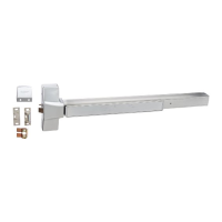
The Hager 4500 Series Surface Vertical Rod Exit Device is a Grade 1 panic hardware or fire exit hardware solution designed for commercial and institutional applications. This document covers the 4500S Surface Vertical Rod Device, 4500SF Fire Exit Surface Vertical Rod Device, 4500S Less Bottom Rod (LBR) Device, and 4500SF Fire Less Bottom Rod (LBR) Device.

Function Description:

The device provides a secure and reliable means of egress, allowing occupants to exit a building quickly and safely during an emergency. When the push bar is depressed, both the top and bottom latches retract, opening the door. For panic hardware, the latches remain retracted as long as the push bar is held, and for fire exit hardware, the latches will extend to secure the door once the push bar is released and the door closes. The LBR (Less Bottom Rod) devices are designed for specific applications where a bottom rod is not required, often used in conjunction with auxiliary fire latches for fire-rated double door installations.

Important Technical Specifications:

  • Door Width Range: The exit device comes in two models: a 36" model for door widths from 30" to 36", and a 48" model for door widths from 36" to 48". For other door widths, the device can be cut to length, with the recommended overall length being the door width minus 4 inches.
  • Mounting Height: The horizontal centerline of the exit device should be measured at 40" from the finished floor.
  • Mounting Hole Placement: The vertical centerline for the exit device mounting holes, top latch mounting holes, and bottom latch mounting holes is 2 7/16" from the edge of the door (or stop face).
  • Trim Actuator Clearance Hole: If mounting trim, a 1/2" [13] diameter clearance hole is required for the trim actuating shaft.
  • Bottom Strike Depth: The cut-out hole for the bottom strike in the finished floor or threshold should be 7/8" deep. The anchor hole for the bottom strike is 1" diameter by 1 1/4" deep.
  • Bottom Latch Throw: The bottom latch should have a 1/2" throw.
  • Top Rod Lengths: Typical top rod lengths vary by door height: 29 1/4" for a 6'-8" door, 33 1/4" for a 7' door, and 45 1/4" for an 8' door.
  • Fasteners:
    • Exit Device Mounting: For metal doors, 1/4"-20 machine screws (4) are used. For wood doors, #12 wood screws (4) are used. For sex bolts, 5/16" clearance holes on the exit device side and 3/8" on the pull side are required.
    • End Cap Mounting: For metal doors/sex bolts, 1/4"-20 machine screws (2) are used. For wood doors, #12 wood screws (2) are used.
    • Bottom Latch Mounting Bracket: For metal doors/sex bolts, 1/4"-20 machine screws (1) are used. For wood doors, #12 wood screws (1) are used.
    • Bottom Strike: 1/4"-20 machine screw and anchor assembly.
    • Top Latch Mounting Bracket: For metal doors/sex bolts, 1/4"-20 machine screws (1) are used. For wood doors, #12 wood screws (1) are used.
    • Top Strike: For metal stops, 1/4"-20 flat head machine screws (3) are used. For wood stops, #12 flat head wood screws (3) are used.
    • Rod Guides: For metal doors, 10-24 machine screws (4) are used. For wood doors, #10 wood screws (4) are used.
  • LBR Device Specific Components:
    • Head Cover Hole Plug – P/N 26490167
    • Auxiliary Fire Latch – P/N 26490166 (Required for Fire Doors)
  • Cylinder Dogging Hardware: Mortise cylinder (1-1/8" to 1-3/8" lengths), standard cam (.723" screw center to tip), 11/32" (8.7 mm) stock solid collar, cash box nut, and Hager cylinder dogging kit.

Usage Features:

  • Door Handing: The device is designed for both RHR (Right Hand Reverse) and LHR (Left Hand Reverse) doors, with clear diagrams illustrating the outside and inside of the door for proper installation.
  • Double Door Applications: The device can be installed on double doors, either with another surface vertical rod exit device or with a rim exit device on the inactive leaf.
  • Fire-Rated Applications: For fire-rated devices, installation must be in pairs of vertical rod devices or with an approved automatic or constant latching flush bolt. LBR devices on fire doors require the Auxiliary Fire Latch (P/N 26490166) to maintain fire listing. The auxiliary fire latch bolt extends into the strike hole in the opposite door, and its black cap and the strike hole plug must melt for the bolt to extend.
  • Dogging Device (Panic Hardware Only): A dogging device is included on panic hardware models (not fire-rated models) to keep the push bar depressed and the latches retracted during high-traffic periods, extending the life of the device.
    • Hex Wrench Dogging: Depress the push bar, insert the hex wrench, and turn clockwise 35° to dog the device. To release, hold the push bar, insert the hex wrench, and turn counterclockwise 35°.
    • Cylinder Dogging: For cylinder dogging, a mortise cylinder with a standard cam is installed. The cam should point away from the push bar. Depress the push bar, insert the key, and turn it clockwise to dog the device. Turn counterclockwise to release.

Maintenance Features:

  • Adjustment Teeth on Bottom Strike: The bottom strike includes adjustment teeth for fine-tuning its distance from the door face, ensuring proper engagement with the bottom latch.
  • Rod Adjustment: If the latches do not operate smoothly when opening and closing the door, the rods can be adjusted.
    • If the bottom latch does not clear the strike or threshold, disconnect the bottom rod from the actuating plate and rotate it clockwise to raise the rod and latch bolt.
    • If the top latch does not clear the strike, disconnect the top rod from the actuating block and rotate it counterclockwise to shorten the overall distance, allowing the top latch to rotate out of the way of the strike.
  • Cover Installation: Chassis head cover and both top and bottom latch covers are installed after the device is adjusted and tested, protecting internal components.
  • LBR Head Cover Plug: For LBR devices, a head cover plug is slid into the bottom slot of the exit device head cover to block the hole from debris or tampering, as no bottom rod is used.

hager 4500 Series Specifications

General IconGeneral
Brandhager
Model4500 Series
CategoryDoor Opening System
LanguageEnglish

Related product manuals