EasyManua.ls Logo

hager 5400 Series - User Manual

hager 5400 Series
6 pages
Print Icon
To Next Page IconTo Next Page
Loading...
2
1
2
1
2
1
2
1
PARALLEL
ARM BRACKET
REGULAR ARM/TOP
JAMB SHOE
CONNECTING ROD
FOREARM
SCREW
SCREW PACK
MAIN ARM
CLOSER ARM
PINION CAP
LATCH VALVE
SWEEP VALVE
HAGER COMPANIES 139 Victor Street, St. Louis, MO 63104 • (800) 325-9995 • Fax (800) 782-0149
TOOLS REQUIRED
COMPONENT PARTS
METAL
1/4"- 20
#7
3/16"
WOOD
Self Drilling Screws
Wood and Metal
For wood, drill 3/16" hole
Sleeve Nut and Bolt
Drill 9/32" thru from Closer Side
3/8" Drill other Side
Machine Screws
#7 Drill, 1/4"- 20 Tap
An incorrectly installed or
improperly adjusted door closer
can cause property damage or
personal injury. These installation
instructions should be followed
to avoid the possibility of
misapplication or misadjustment.
NOTE: For special applications, a separate door
and frame preparation template is packed with
these instructions. Use this instruction sheet for
installation sequence and closer adjustments only.
Dimensions are based on standard doors and
frames with 1/8" clearance, 5/8" stops, and
square edge doors.
Door and frame must be properly reinforced.
Non-Handed Door Closers.
• These door closers should NOT be installed on the exposed side (weather side) of exterior doors.
Regular Arm
Installation
See Page 2
Left Hand Door - LH
Right Hand Reverse - RHR
Regular Arm
Installation
See Page 2
Right Hand Door - RH
Left Hand Reverse - LHR
Top Jamb
Installation
See Page 5
Top Jamb
Installation
See Page 5
NOTE: For Top Jamb
Application
Left Hand Door - LH
Right Hand Reverse - RHR
Right Hand Door - RH
Left Hand Reverse - LHR
Parallel Arm
Installation
See Pages
3 & 4
Parallel Arm
Installation
See Pages
3 & 4
Left Hand Door - LH
Right Hand Reverse - RHR
Right Hand Door - RH
Left Hand Reverse - LHR
A longer connecting
rod is required for
reveals greater
than 3" (76mm)
Reveal
5400 Series Non-Hold Open Door Closer
Installation Instructions
Available in Sizes 2, 3, 4 and 5
Check building and fire codes to
see if your application requires
the use of sleeve nuts and bolts.
Question and Answer IconNeed help?

Do you have a question about the hager 5400 Series and is the answer not in the manual?

hager 5400 Series Specifications

General IconGeneral
DutyContinuous
Fire RatedYes
Dynamic Strength5400N
Holding Force5400N
MaterialZinc

Summary

Regular Arm Installation Guide

Regular Arm Parts Identification

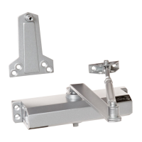
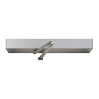
Lists and identifies all components included for regular arm installation.

Marking and Drilling Holes for Regular Arm

Detailed instructions on marking and drilling procedures for closer body and jamb shoe mounting.

Installing the Door Closer Body (Regular Arm)

Procedure for mounting the closer body to the door, ensuring correct orientation.

Installing the Main Arm (Regular Arm)

Instructions for orienting and attaching the main arm to the closer spindle.

Connecting Main Arm and Closer Rod

Steps to connect the main arm to the connecting rod at a 90° angle.

Adjusting Door Closer Settings

Guidance on adjusting sweep speed and latch speed for optimal closer function.

Installing the Pinion Cap

Final step to install the pinion cap onto the unused closer body spindle.

Parallel Arm Installation Guide

Parallel Arm Parts Identification

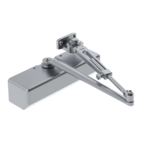
Lists and identifies all components included for parallel arm installation.

Marking and Drilling Holes for Parallel Arm

Detailed instructions on marking and drilling for closer body and bracket mounting.

Installing the Closer Body (Parallel Arm)

Procedure for mounting the closer body to the door, ensuring correct orientation.

Installing the Connecting Rod

Instructions for removing regular arm shoe and attaching the connecting rod.

Installing the Main Arm (Parallel Arm)

Steps for orienting and attaching the main arm to the spindle for parallel application.

Connecting Main Arm and Connecting Rod

Details on screwing the connecting rod into the main arm forearm and tightening.

Adjustments for Parallel Arm Closer

Guidance on adjusting sweep and latch speeds for the parallel arm installation.

Installing the Pinion Cap (Parallel Arm)

Final step to install the pinion cap onto the unused closer body spindle.

Top Jamb Installation Guide

Top Jamb Parts Identification

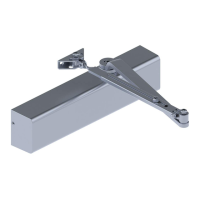
Lists and identifies all components included for top jamb installation.

Marking and Drilling Holes for Top Jamb

Instructions for marking and drilling for closer body and connecting rod shoe mounting.

Installing the Closer Body (Top Jamb)

Procedure for mounting the closer body to the top jamb, ensuring correct orientation.

Installing the Main Arm (Top Jamb)

Steps for orienting the main arm and attaching it to the closer spindle.

Connecting Main Arm and Connecting Rod

Details on screwing the connecting rod into the main arm and positioning it.

Adjustments for Top Jamb Closer

Guidance on adjusting sweep and latch speeds for the top jamb installation.

Installing the Pinion Cap (Top Jamb)

Final step to install the pinion cap onto the unused closer body spindle.

Door Closer Adjustments and Specifications

Sweep Speed Adjustment

How to adjust the sweep speed for proper door closing time (3-7 seconds).

Latch Speed Adjustment

Procedure to adjust latch speed to ensure the door closes and latches securely.

Optional Backcheck Adjustment

Instructions for adjusting backcheck to prevent excessive opening speed.

Spring Power Adjustment and Sizing

Table showing recommended closer sizes based on door width and type.

Adjustment Diagram and Controls

Visual guide to door closer adjustment ranges: Sweep, Backcheck, Latch.

Arm Placement in Shoe

Diagram illustrating arm placement options for increased or decreased strength.

Related product manuals