4500/4600 Series Electric Exit Device
Installation Instructions
I-ED00367
Rev 8, Rev Date: 8/27/2018 27390025 Page 2 of 3
Hager Companies 139 Victor Street, St. Louis, MO 63104 (800) 325-9995 www.hagerco.com
Notes:
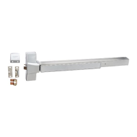
1. Wire entry hole location on door (see example below):
a. This dimension depends on the backset and specific door application. Please see exit device
instructions to determine backset and exit device location.
b. This dimension also depends on whether the device length has been field modified. Please note
that the standard 3-foot exit device with ELR and Electric Dogging cannot be cut from the factory
length. Standard 3 foot exit devices with MLR can be cut a maximum of two inches.
Example – Single 3-foot door with RIM device. Please refer to individual 4500/4600 Series Installation template for approprite dimension.
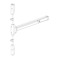
2. Mount exit device end cap and wires:
a. Follow exit device instructions and template to install end cap bracket.
b. Route wires as shown in diagram below and terminate at power transfer device.
3. The EL, EU functions for the Mortise Exit Device are available for the Night Latch Version only (4501N).
These electrifications are ordered with the device but are included in the Mortise Exit Lock Body.
4. The ELR, MLR, DE and ED all occupy the same space in the push bar. None of these can be done in
conjunction with each other or with cylinder dogging or any Alarm Kit functions.