236
ldentification:
• Master unit: by setting DIP switch, the unit number is 0. It is used to communicate with indoor unit, and it is the
organizer of outdoor communications as communication master unit.
• Slave unit: by setting DIP switch, the unit number is not 0.
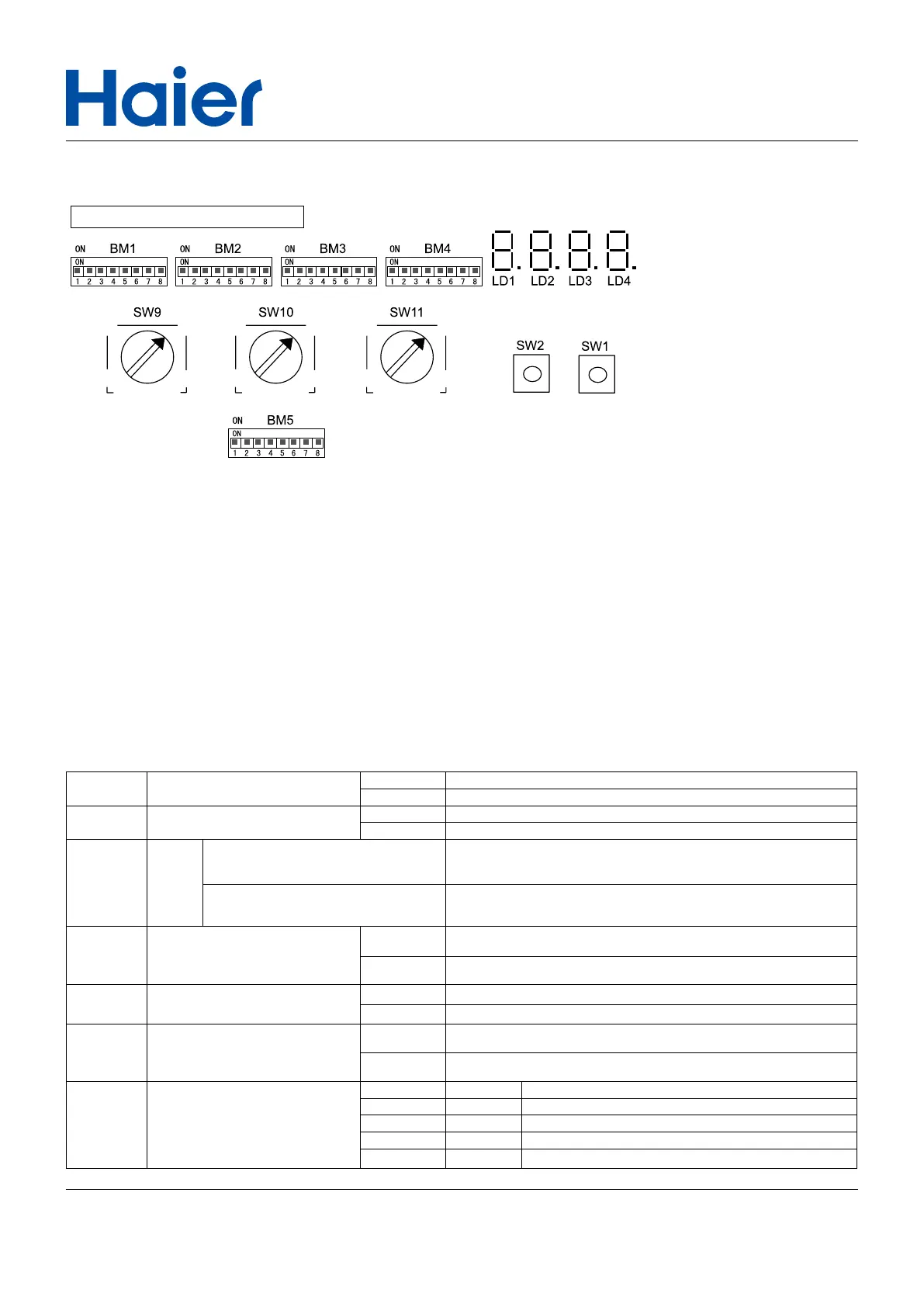
• DIP switch definition:
BM1 is usually set by the personnel on site; BM2, BM3, BM4 are pre-set in the factory.
BM1_1: Master outdoor unit searches the total outdoor units after powered on at first time. The quantity of total
outdoor units is floating from right to left on LED. "1=0" is one outdoor unit, "2=01" is two outdoor units, "3=012" is
three outdoor units.
BM1_2: Master outdoor unit searches the total indoor units after powered on at first time. The quantity of total
indoor units is floating from right to left on LED. "-04-" is 4 indoor units, "-06-" is 6 indoor units, "-15-" is 15 indoor
units.
BM1_3: The setting is 0 or 1. Default is 0. Once powered off, unit software shall reset to "OFF" automatically ignoring
BM1_3 setting.
1)BM1 instruction
BM1-1 Outdoor searching after startup
0 Begin to search outdoor
1 Stop searching outdoor and lock the quantity
BM1-2 Indoor searching after startup
0 Begin to search indoor
1 Stop searching indoor and lock the quantity
BM1-3
Start
up
Power on, no action
Default condition: Unit shall startup after 6 hours preheat or oil superheat
above 20°C. (Oil Superheat=Oil temperature of compressor sink-
Refrigerant saturation temperature of ambient)
Power on, change 0 to 1 or change from 1
to 0 then to 1
Unit shall startup after 6 hours preheating or oil superheat
above 15°C
.
BM1-4 Heating function
0 Ambient Temp.>25°C, heating function normally
1 Ambient Temp.>25°C, heating running forbidden
BM1-5 Over match setting
0 Indoor capacity divisity >130%, system functions normally
1 Indoor capacity>130%, system alarms
BM1-6
Communication protocol selection
between indoor and outdoor unit
0 New protocol
1 Old protocol
BM1-7
BM1-8
Address setting
BM1-7 BM1-8 unit number
0 0 0# (physical master unit)
0 1 1#
1 0 2#
1 1 3#
16. Outdoor PCB dip switch setting
Selection switch and the display
 Loading...