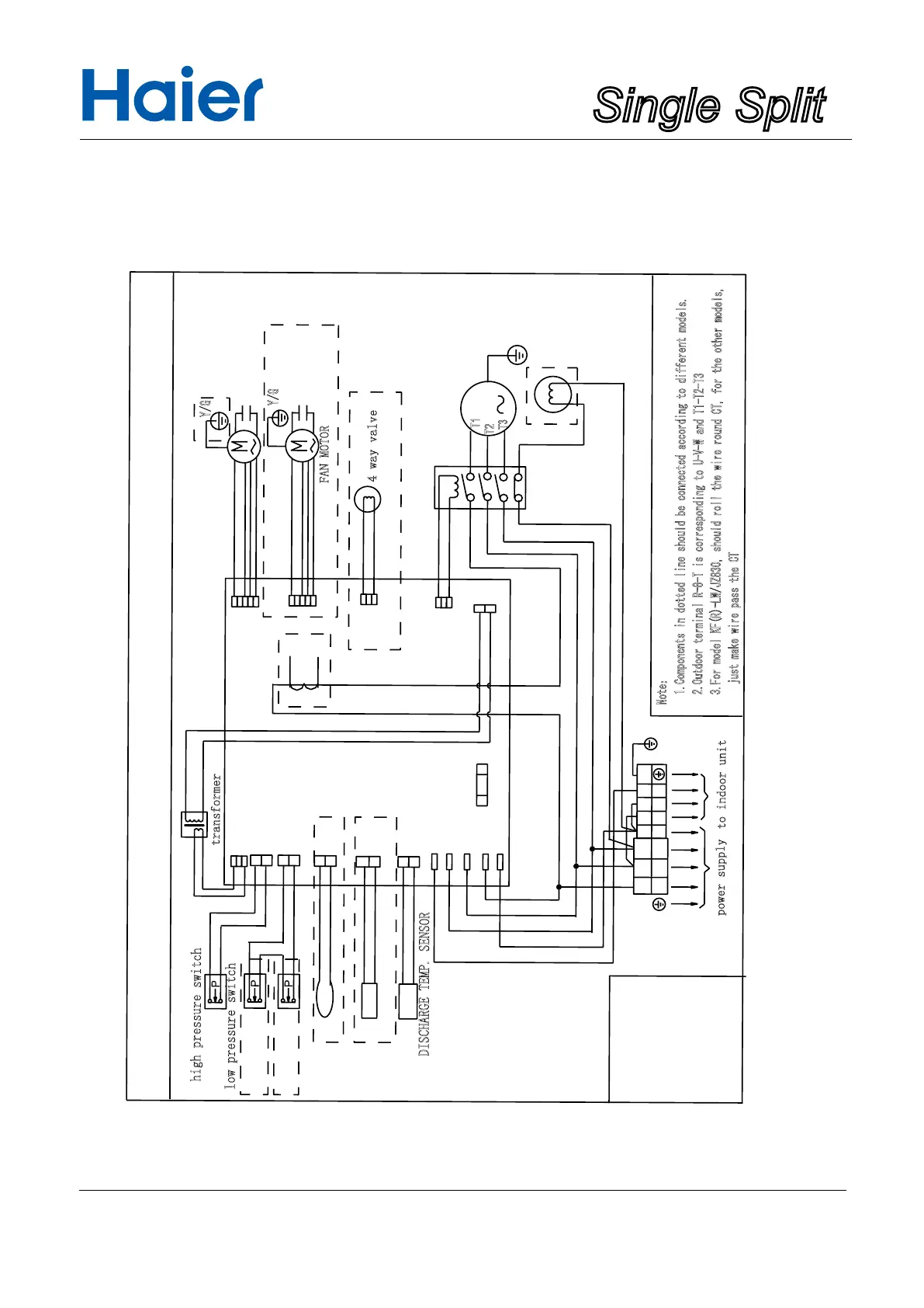
outdoor wiring diagram
0150509745
B:BLACK
Y:YELLOW
BL:BULE
Discharge protection of compressor
DEFROST TEMP. SENSOR
Y/G:YELLOW/GREEN
R:RED
CN2
CN10
CN1
CN3
CN12
CN11
W
W:WHITE
R
BL
B
B
R
S
T
R
N
S
L2
L1
L3
N
1
2
Y/G
Y/G
3
T3.15A/250VAC
fuse
Note:
1.Components in dotted line should be connected according to different models.
2.Outdoor terminal R-8-T is corresponding to U-V-W and T1-T2-T3
3.For model KF(R)-LW/JZ830, should roll the wire round CT, for the other models,
just make wire pass the CT
CN4
CN14
CN7
CN5
CN13
BL BL
B
Y/G
R R
T1
T2
T3
W W
M
CT
Y/G
Y/G
high pressure switch
low pressure switch
FAN MOTOR
CAPACITOR
FAN MOTOR
CAPACITOR
4 way valve
magnetic contactor
compressor
heater
transformer
AMBIENT TEMP. SENSOR
DISCHARGE TEMP. SENSOR
to indoor unit
power supply