93
Outdoor 1 Outdoor 2 Outdoor 3 Outdoor 4
P
Q A B C
P
Q A B C
P
Q A B C
P
Q A B C
CN24
IGU09
Communication wiring gure (wireless)
B. One wired controller controls one indoor unit, as shown in the above gure (indoor unit 6-19). The indoor unit
and the wired controller are connected via three lines with polarity.
C. Two wired controllers control one indoor unit, as shown in the gure (indoor unit 20). Either of the wired
controllers can be set to be the master wired control while the other is set to be the slave wired controller. The
master wired controller, slave wired controller and indoor units are connected via three lines with polarity.
P
Q
P
Q
P
Q
P
Q
P
Q
Indoor 1 Indoor 2 Indoor 3 Indoor 4 Indoor n
CN34
IGU10
CN34
IGU10
CN34
IGU10
CN34
IGU10
CN34
IGU10
When the outdoor unit is combined, only the host machine is installed IGU09, and the sub machine is connected
with the main machine through the communication terminal of the A/B/C.
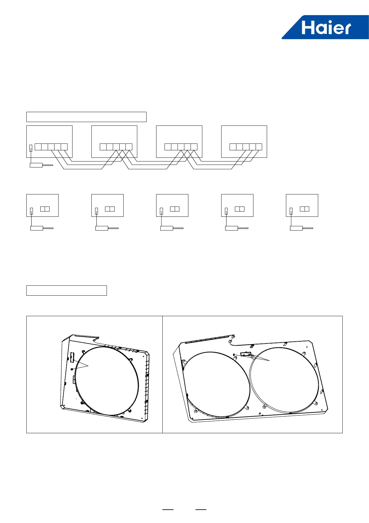
IGU09 installation method
IGU09
IGU09
Single fan Double fan
1. Remove the outdoor unit cover, install the IGU09 in the slot inside the top cover, and use the tape (self) xed.
Place the IGU09 antenna down 90 ° at right angles.
Note:
If the system unit adopts Zigbee wireless communication, it must adopt wireless and wired hybrid mode, that is,
wired communication between the host outdoor unit and the rst valve box, wireless communication between the
valve box and the connected indoor units. Wired communication is used between the valve box and the valve box
and between the valve box and the single cold indoor units (the indoor units not connected to the valve box).
 Loading...