www.haiwell.com Haiwell PLC - Analog Module User Manual
Analog Module User Manual
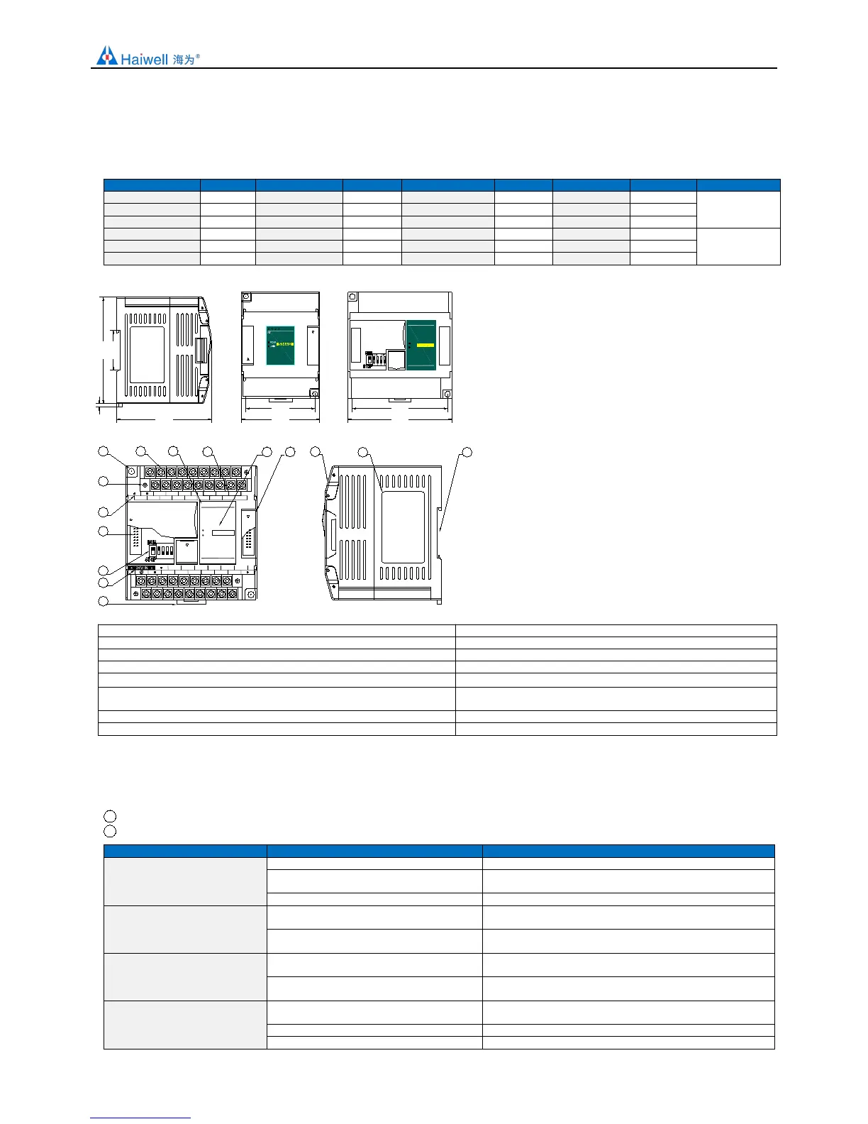
1. Product Model List and Dimension
84.5
93.0
61.5
70.0
0 1 2 3
0 1 2 3
S08XA2
AI
AQ
LINK
POW
84.0
35.0
95.0
3.0
0 1 2 3
4 5
6
7
AI
AI
LINK
POW
AI1V
AI0I
AI2I
AI0V
AI2V
AI0G
AI2G AI3I
GND
AI3V
A+
AI1I
B-
AI1G AI3G
RS485
AI4I
AI6I
AI4V
AI6V
AI4G AI5I
AI7V AI7GAI7I
AI5V AI5G
AI6G
13
14
15
1 2 3
4
ON DIP
12
11
S08AI
1
2
3
4
5
6
7
8 9
10
1
PWR: power indicator. green, constant light -Power normal; Not light - Power abnormal.
2
LINK: multi-status indicator . three colors (Red. Yellow. Green), as follow:
Reference processing mode
No communication of module
MPU has identified the module but no
communication
Serial or parallel port in communication
Green jitter: indicator on 30ms and off 30ms
Parallel power supply not
enough, must connect to external
power supply
Without serial or parallel port in
communication
Yellow flicker: indicator on 0.5s and off 0.5s
With serial or parallel port in communication
Yellow is darkened and jitter alternately: indicator off 0.5s and
jitter 0.5s
Firmware upgrade failed,
reupgrade the module firmware
Without serial or parallel port in
communication
Red flicker: indicator on 0.5s and off 0.5s
With serial or parallel port in communication
Red is darkened and jitter alternately: indicator off 0.5s and
jitter 0.5s
Hardware failure and
maintenance
Without serial or parallel port in
communication
With serial or parallel port in communication
Red jitter quickly: indicator on 30ms and off 30ms
2. Removable terminal screw
9. Analog input channel indicator
10. RS485 communication port
11. PWR power indicator, LINK module communication indicator
5. DIP switch(4-channel module without DIP switch)
12. Module expansion port
6. External power supply terminal
(DC24V and AC220V, Generally powered by the host PLC)
13. Transparent cover of module terminal
 Loading...