(temperature, humidity, pressure, air volume, flow, fan speed, valve opening and so on). The Distributed installation control and
unrestricted expansion are easily realized, which greatly improves the control system. It reduces the wiring cost of all kinds of
signals, and reduces the interference caused by the over-length of the analog signal line.
Next, we will introduce remote IO usage.
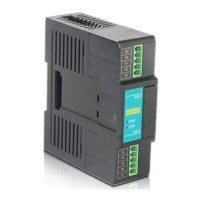
1. Load Cell Module power supply
When load Cell Module is used for remote IO,24VDC external switch power supply, PWR indicator light is on.
2. Communication interface introduction
H01WG has the RS485 interface.
3. Communication protocol and default parameters
RS485:
It supports standard Modbus RTU/ASCII protocol, and it can communicate with any third-party devices, such as PC scada, touch
screen, text display and PLC, which support Modbus protocol.
Soft address: by programming software, the address set by remote tool, the address range 1-254, the default value is 1;
Baud rate: 2400, 4800, 9600, 19200, 38400, 57600, 115200 optional;
Data format: N,8,2 RTU、 E,8,1 RTU、 O,8,1 RTU、 N,8, 1 RTU、E,7,1 ASCII、 O,7,1 ASCII、 N,7,2
ASCII
RS485 default parameters: 19200, N 82 RTU, station number 1.
4.When Module is used for remote IO, Module communication parameter configuration method is introduced as
folllows:
There are three methods for remote IO parameter configuration:
①It can be configured by programming software tool remote Module (recommended).
②The Module can be connected to the host plc by parallel port and configured by hardware configuration and TO instruction.
③The Module can be configured by MODW instruction through serial communication
5.Parameter configuration example: configuring the Module through programming software “remote Module tool”.
Hardware connection
①.through the RS485 (A+ B- terminal) connection: the computer with the serial port, can use 232 to 485 converter, if the PC with
USB interface, you can use USB to 485 converter.
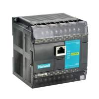
②.connect via Ethernet + communication interface: the Module can connect directly to the computer network port with standard
network cable, or the computer and Module will be connected to the Ethernet switch.
Software operation steps
Click on the software menu bar - "remote Module":