en.haiwell.com Haiwell PLC -- Load Cell Module User Manual
Load Cell Module User Manual
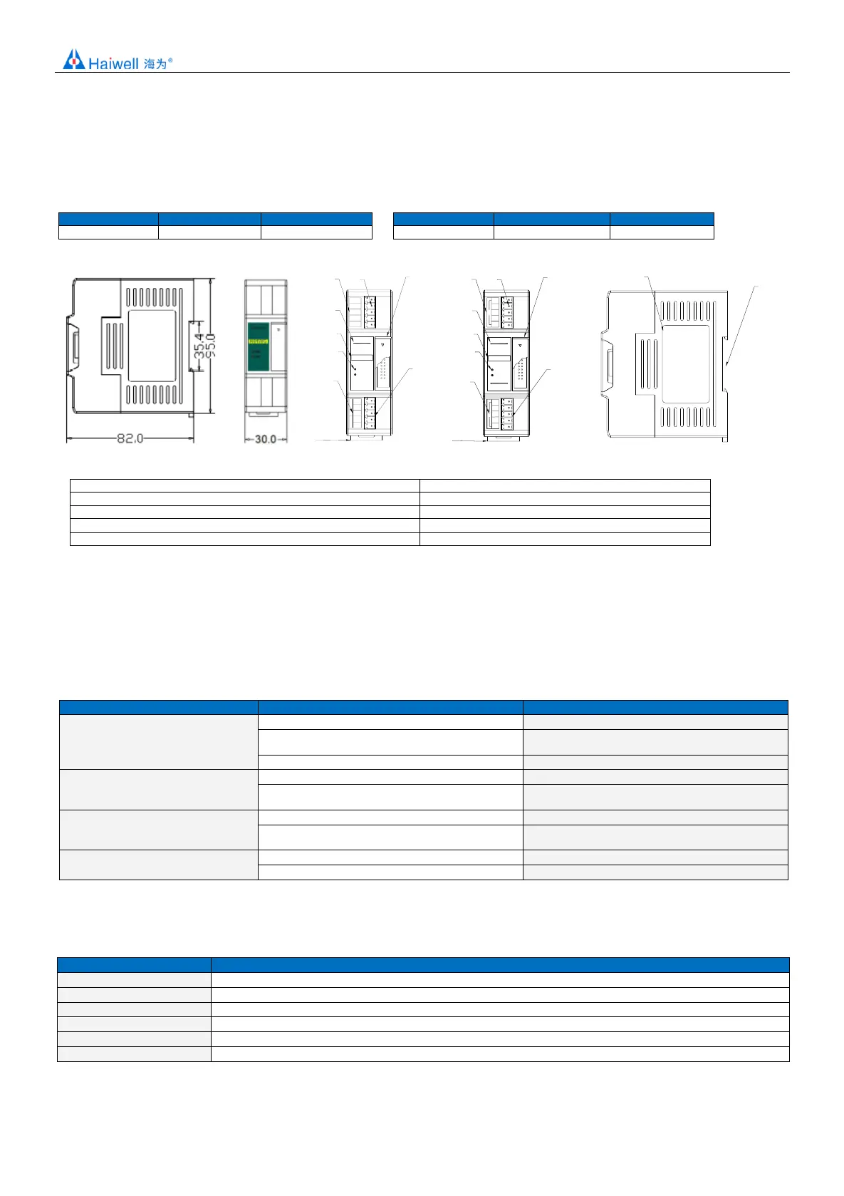
1. Product Model List and Dimension
0 1 2 3
LINK
PWR
LINK
H01WG
⑧
⑨
①
②
③
④
①
⑤
⑥
⑦
⑥
EXC+
EXC-
SHD
SIG+
SIG-
A+
B-
GND
24V
0V
RS485
DC IN
0 1 2 3
PWR
LINK
H02WG
①
②
③
④
①
⑤
⑥
⑦
⑥
EXC+
EXC-
SHD
SIG+
SIG-
CH2
0 1 2 3
CH1
CH2
EXC+
EXC-
SHD
SIG+
SIG-
CH1
⑧
⑨
2. Weighing status indicator
8. Transparent cover of Module terminal
4. PWR:power indicator、LINK:Module communication indicator
5. DIN rail mounting slot
2. Indicator Description
(1) PWR:Power indicator. Green, power is normal; No light - power is abnormal.
(2) Weighing Status Indicator: 0:ON-netweight; OFF-gross weight; 1:ON-No load; 2:ON-weight limit exceeded; 3:ON-measuring
stability.
(3) LINK: Multi-status indicator .three colors(Red. Yellow. Green). As follows:
Reference processing mode
No communication of Module
MPU has identified the Module but no
communication
Serial or parallel port in communication
Green jitter: indicator on 30ms and off 30ms
Parallel power supply insufficient, must
connect to external power supply
Without serial or parallel port in communication
Yellow flicker: indicator on 0.5s and off 0.5s
With serial or parallel port in communication
Yellow indicator off and jitter alternates: indicator off
0.5s and jitter 0.5s
Firmware upgrade failed, re-upgrade
the Module firmware
Without serial or parallel port in communication
Red flicker: indicator on 0.5s and off 0.5s
With serial or parallel port in communication
Red indicator off and jitter alternates: indicator off
0.5s and jitter 0.5s
Without serial or parallel port in communication
With serial or parallel port in communication
Red jitter quickly: indicator on 30ms and off 30ms
3.Power Supply Specification
DC input power polarity reverse, over voltage protection