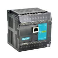
10. Mounting and Installation
The PLC should be secured to an enclosed cabinet while mounting. For heat dissipation, make sure to provide a minimum
clearance of 50mm between the unit and all sides of the
cabinet.
Rail mounting: Use standard 35 mm rail.
Screw mounting: Each MPU or extension Module has two
positioning screw holes, the diameter of the hole is 4.5mm.
Please refer to the dimension figure for the location of the
positioning holes and their spacing.
To avoid over temperature and for a better heat dissipation,
do not mount PLC to a position near to the bottom/top of the
cabinet. Do not mount PLC in vertical direction.
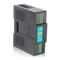
Extension Module wiring: Connections between extension Modules and connections between Module and MPU are achieved
through bus.A extension cable will be configured to every extension Module, for the connection between two different
Modules.Connection methods: turn the right side of extended interface(the last MPU or extension Module) over, plug the
extension cable in the extended interface, then press down the cover of the extended interface to reset the interface, the extended
interface at the right side of the Module will be reserved for extension of the next Module. Connect all extension Modules in turn in
the same way.