en.haiwell.com Haiwell PLC -- Load Cell Module User Manual
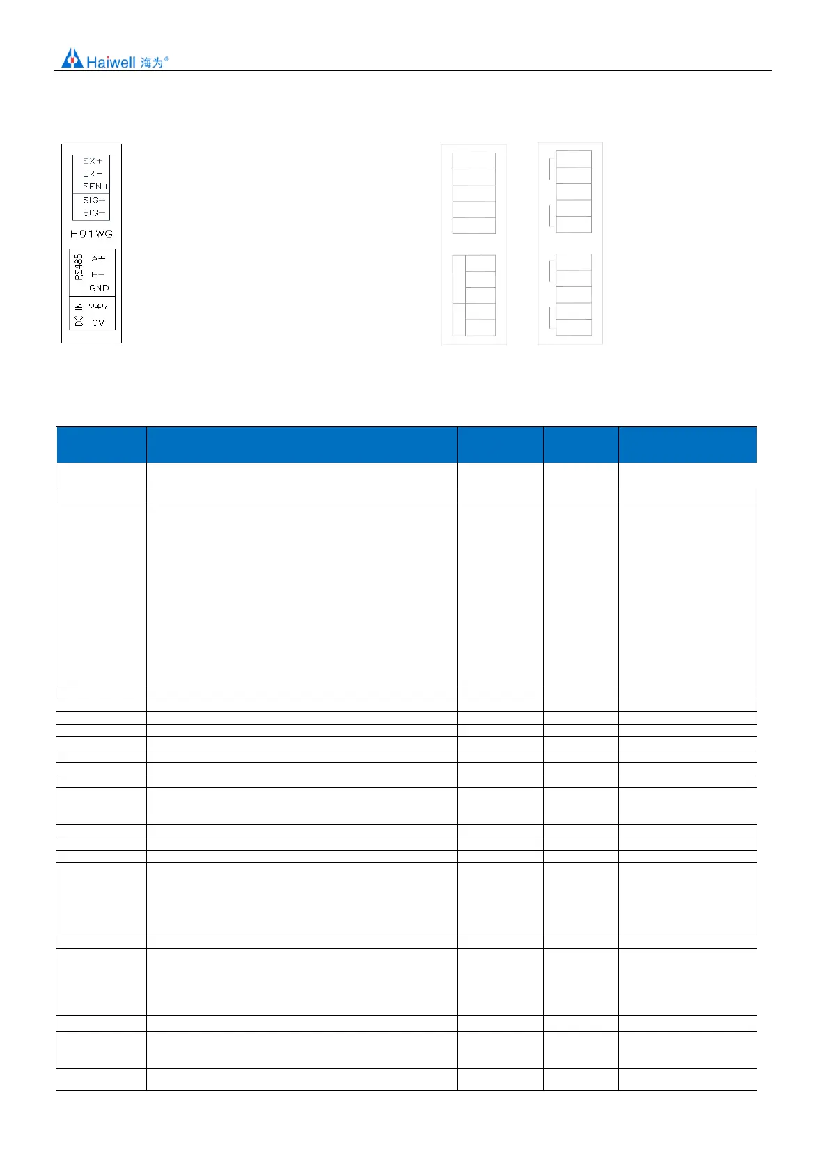
First generation module terminal: Second generation module terminal:
H01WG
24V
0V
A+
B-
DC IN
SIG+
SIG-
GND
RS485
EXC+
EXC-
SHD
H02WG
SIG+
SIG-
EXC+
EXC-
SHD
SIG+
SIG-
EXC+
EXC-
SHD
CH1
CH2
9. Module parameter table (CR code means the corresponding Modbus register address)
Note: CR code is corresponding to the Modbus register address.
CR code(Hex)
communicatio
n address
Low byte for Module code, Higher 3-bit of the High-Byte is ID
number. Lower 5-bit of High-Byte is version number.
Communication Protocol
Low byte lower 4-bit:0 - N,8, 2 For RTU
1 - E,8, 1 For RTU
2 - O 8, ,1 For RTU
3 - N,7, 2 For ASCII
4 - E,7, 1 For ASCII
5 - O,7, 1 For ASCII
6 - N,8, 1 For RTU
Low byte higher 4-bit:0 – 2400
1 - 4800
2 - 9600
3 - 19200
4 - 38400
5 – 57600
6 - 115200
IP Address: default 192.168.1.111
IP Address: default 192.168.1.111
High byte subnet mask( b3~b0,”1” means 255, “0” means 0, for
example subnet mask 255.255.255.0 b3~b0=1110), low byte
manufacturer code HW
Low byte code cannot be
modified
Error Code
0:normal
1: illegal firmware identity
2: firmware incomplete
3:system data access exception
4: No external 24V power supply
Channel 1 status code
bit0:No-load( zero point weight)
bit1:exceed the upper limit of weight
bit2:measurement value stable
bit3~15:reserve
Channel 1 real-time weight
Channel 1 uses 32-bit display flags:
0: 16-bit weight display
1: 32-bit weight display
Channel 1 Real-time Weight 32 Bit Value:
14H: 32-bit low byte