5
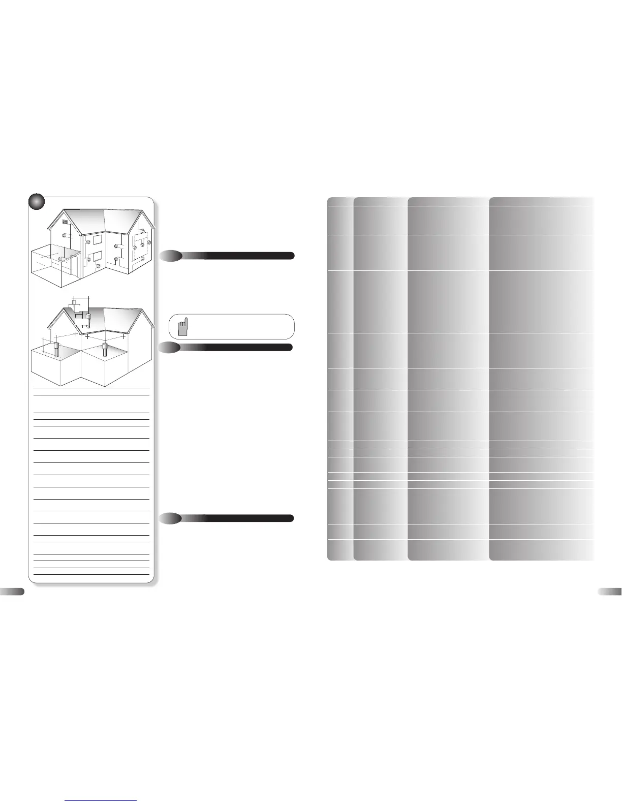
FLUE TERMINAL POSITION
Position Minimum spacing
A Directly below an openable window, 300mm 12in
air vent, or any other ventilation
opening
B Below gutter, drain/soil pipe 75mm 3in
C Below eaves 200mm 8in
D Below a balcony 200mm 8in
*2500mm 98in
E From vertical drain pipes and 150mm 6in
soil pipes
F From internal or external corners 300mm 12in
*internal corners *1000mm 40in
G Above adjacent ground or
balcony level 300mm 12in
H From a surface facing the terminal 600mm 24in
*2500mm 98in
I Facing terminals 1200mm 48in
*2500mm 98in
J From opening (door/window) in 1200mm 48in
carport into dwelling *not recommended
K Vertically from a terminal on the 1500mm 60in
same wall
L Horizontally from a terminal on the 300mm 12in
same wall
M Adjacent to opening 300mm 12in
N Below carport 600mm 24in
*not recommended
O From adjacent wall 300mm 12in
P From adjacent opening window 1000mm 40in
Q From another terminal 600mm 24in
R Minimum height 300mm 12in
•
•
•
•
•
•
•
•
•
•
•
•
•
•
•
•
•
•
•
•
•
•
•
•
•
•
•
•
•
•
•
•
•
•
•
•
•
•
•
•
•
•
•
•
•
•
•
•
•
•
•
•
•
•
•
•
A
B,C
G
K
M
A
E
F
F
K
B,C
G
G
K
K
L
L
J
F
H,I
D,N
C
Q
O
O
P
R
SPECIAL REQUIREMENTS FOR A
VERTICALLY BALANCED FLUE
300mm
Min
430mm
Min
10
d) If the appliance is installed in a room or internal space with other
opened flued appliances, the aggregate maximum rated input shall
be used to determine the air vent free-area. (BS 5440-2 Table 2).
e) Where an open flued system is used, and the flue duct air
inlet is within a compartment then high and low level air vents are
necessary in the compartment, the size of the vents should be
calculated in accordance with BS 5440-2 Table 2.
3.5
CONDENSATE DISPOSAL
The condensate drain connection is suitable for either 21.5 mm or
22 mm plastic push fit or adhesive overflow pipes and fittings. It
should be piped to drain, preferably within the building, maintaining
a continuous 2.5° fall away from the appliance. If the drain is routed
to outside it should be to a drain or soak away, and any external
pipe work should be in 32 mm. Insulation to protect from freezing in
cold weather conditions is also advisable.
3.6
GAS SUPPLY
a) The Gas Supplier should be consulted at the installation planning
stage in order to establish the availability of an adequate supply of gas.
b) An existing service pipe MUST NOT be used without prior
consultation with the Gas Supplier.
c) A gas meter can only be connected by the Gas Supplier or by their
contractor.
d) An existing meter and/or pipe work should be of sufficient size to
carry the maximum appliance input plus the demand of any other
installed appliance. (BS 6891: 1988).
A minimum of 22 mm diameter pipe work is
recommended within 1000 mm of the appliance gas cock.
e)
Natural gas appliances: The governor at the meter must give a
constant outlet pressure of 20 mbar (8 in.wg) when all appliances on
the system are running.
Propane appliances: The regulator must give a constant outlet pressure
of 37 mbar (14.9 in.wg) when all appliances on the system are
running.
f) The gas supply line should be purged. WARNING: Before purging
open all doors and windows, also extinguish any cigarettes, pipes, and
any other naked lights.
g) The complete installation must be tested for gas tightness.
3.7
CENTRAL HEATING SYSTEM
a) The appliances are designed for open vented central heating
water systems, but may be fitted to a sealed central heating
system provided the necessary components, such as expansion
vessel and pressure safety relief valve are fitted to the system.
Refer to Figure 8 for a typical open vented system design, which
incorporates radiators, and a drain facility that must be provided
at the lowest point in the system to allow complete drain down.
b) The installation should be designed to operate with a flow
temperature of up to 95°C.
*Recommended by the boiler manufacturing industry to prevent
pluming nuisance and damage to buildings.
If the appliance is installed in a garage all pipe work
should be in 32 mm. Ensure that the condensate discharge
system complies with any local regulations in force.
LED CODE FAULT/EFFECT REASON ACTION
● Check no air is in heat exchanger/CH system
1 Overheated appliance Water temperature greater than 105 °C
● Check external pump operation
● Check PCB/X1C connector
● Check flow thermistor
Water flow failure or
● Check water pressure
Differential check faulty/
● Check external pump/ CH system blockage
2
Flame for a short
Sensor temperature differential incorrect
● Check no air is in heat exchanger/CH system
period only
● Check flow, and return sensors
● Check wires to sensors not crossed
● Check gas supply
● Check gas service cock
● Check gas valve and lead
No gas or Lockout flame Low gas pressure.
● Check detection electrode/lead
3signal/ No flame, Lockout No flame signal on ignition,
● Check gas supply
after 5 ignition attempts or loss of signal during operation
● Check gas valve and lead
● Check PCB/X2A & X2B connectors
● Check spark generator/spark electrode
● Check mains earth lead continuity
● Check flue sensor
● Check flue system
4Flue gas sensor/No flame Flue gas temperature greater than 95 °C
● Check no air is in heat exchanger/CH system
● Check external pump
● Check PCB/PCB connectors
● Check flow, return and flue sensors
5 Defective sensor/No flame Defective flow, return or flue sensor
● Check wiring to sensors
● Check PCB/X6 & X8 connectors
Defective gas valve/
5 sec flame signal after burner
●
Check gas valve and lead
6Flame continues after
is switched off
●
Check PCB
demand ends
● Check fan
7 Defective fan/No flame Missing or Erroneous RPM signal
● Check mains fan lead & connector
● Check low voltage fan lead & connector
● Check PCB/X3 connector
APCB error/No flame Internal error ● Check PCB
b Activate BCC/No flame New BCC ● Turn CH control knob to reset twice to activate
C
Safety system failure/
Failure of internal self checking system
● Check PCB
No flame ● Check BCC is initialised
E BCC error/No flame Incorrect /missing BCC ● Reseat or replace BCC
hNo flame Faulty connector ● Check PCB/X1A connector
● Check water pressure
Differential check faulty/
● Check external pump/ CH system blockage
O
Flame for 15 seconds
Water flow rate too low
● Check no air is in heat exchanger/CH system
● Check flow, and return sensors
● Check wires to sensors not crossed
P
Error in power supply/
Low mains voltage
● Check mains voltage
No flame ● Check PCB connectors
● Check power supply
No light indication Defective power supply
● Check PCB/X1B connector
● Check PCB fuse
27