19
a) Slacken the screw in the appliance inlet pressure test point
and connect a suitable manometer. Refer to Figure 23.
b) Check that the gas supply is turned ON and the gas service
cock is OPEN.
c) Switch on the electrical supply.
d) Turn the CH temperature Control knob to the midpoint between the
minimum and maximum setting. The display changes from 'o' to 'h'.
COMMISSIONING & TESTING
5
5.1
FILLING THE WATER SYSTEM
Before commissioning the appliance, the whole gas installation
including the meter MUST be purged and tested for gas tightness
in accordance with BS 6891: 1988.
Open all doors and windows, extinguish naked lights,
and DO NOT SMOKE whilst purging the gas line.
It is recommended, where possible, to flush the CH
system without the appliance fitted, to avoid debris
and flux blocking the waterways within the appliance.
Do not use the pressure relief valve to drain the
system, because dirt or debris could prevent the
valve seating correctly. If the valve leaks or sticks
closed, then replace it.
Before commencing the commissioning procedure, ensure that the
gas service cock is turned on, the electricity supply is isolated,
and that the CH pipe-work is complete. Fill the water systems by
following the procedure detailed below in steps a) and b), and
referring to Figure 20.
20
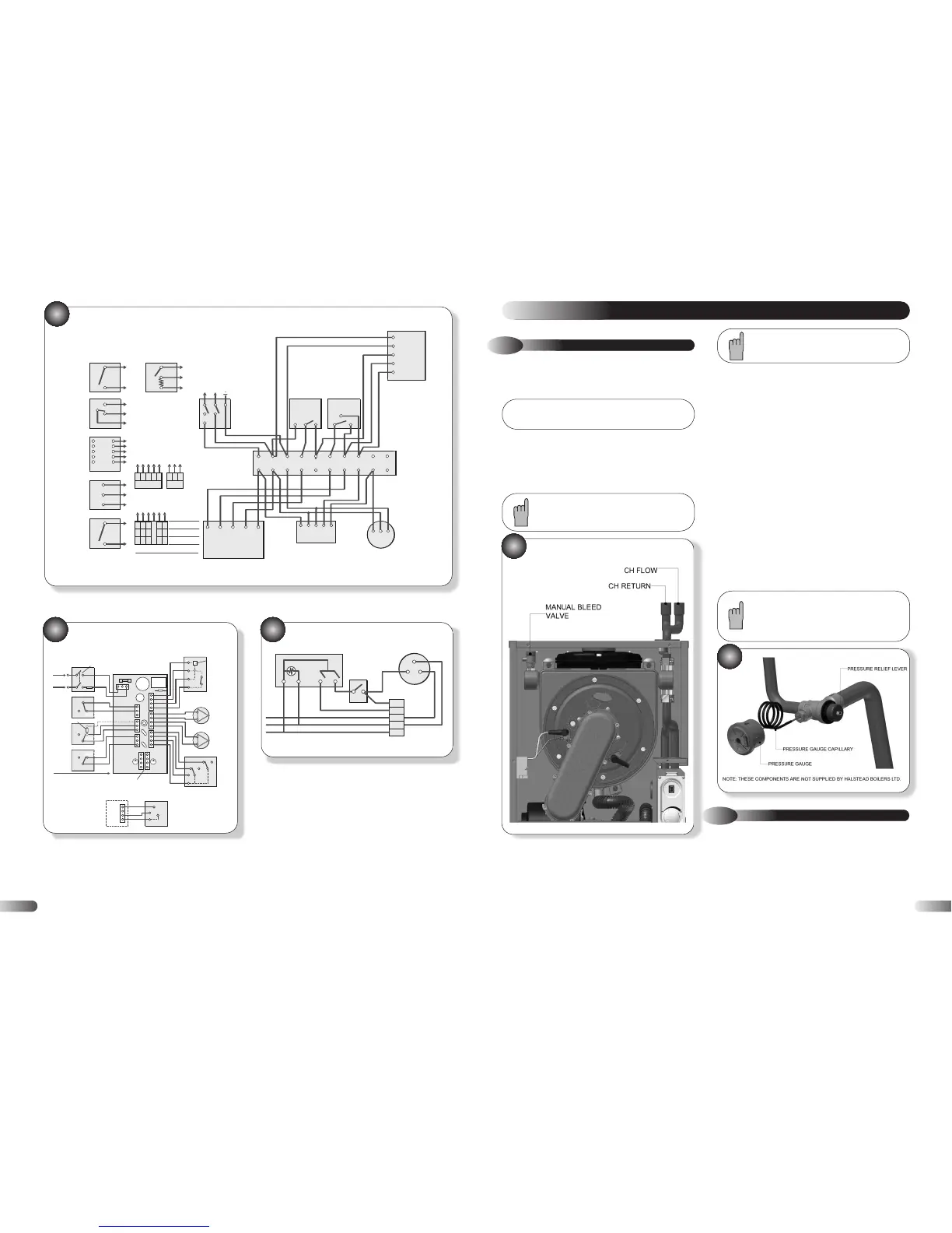
COMMISSIONING THE WATER SYSTEM
To aid venting, a manual air vent is provided on the
LHS of the heat exchanger.
Check the system for soundness.
Drain the entire system to flush out any debris, and refill making
sure that all the air is properly vented from the system and pump.
Repeat this instruction with the system hot. It is recommended that
the system be cleaned with a recognised system cleaner such as
Fernox or Sentinel.
Prior to lighting the appliance to check the gas rates, the central
heating system should be checked for circulation by operating the
appliance with the gas turned off, this is to ensure that no air
locks occur. The appliance may go into ignition lockout and
require resetting.
b) Sealed Systems
Fill the system until the pressure gauge registers 2.0 bar. Clear
any locks and check for soundness.
Check the operation of the pressure relief valve (figure 21) by
lifting the lever on the valve gently to ease the valve of its seat.
Checking that water is discharged, release the lever and ensure
that the valve seats correctly and does not leak. Where this is not
possible a manual check should be carried out.
Release the cold water to the initial design pressure.
!
a) All Systems
A competent person in accordance with the current issue of
BS6798 should carry out commissioning.
Fill the system with cold water. Vent the system via the radiator
valves and system air vents in accordance with normal practice.
Ensure that all system air vents are closed.
New
Drawing
Required
5.2
COMMISSIONING THE APPLIANCE
Refer to Figure 22
21