12
3.17
EXPANSION VESSEL
A diaphragm type expansion vessel, conforming to the current
issue of BS4814 (see also BS7074 Part 1 and 2) must be
connected at a point close to the inlet side of the circulating
pump, see the diagrammatic layout, figure 7 unless laid down
differently by the manufacturer.
The expansion vessel volume depends on the total water system
volume and the initial system design pressure. For any system an
accurate calculation of vessel size is given in the current issue of
BS5449 and BS7074 Part 1.
Example: For an initial design pressure of 0.7 bar, the minimum
total vessel volume required is 0.063 x Total System Volume.
7
SEALED WATER SYSTEM
NOTE: No automatic by-pass required. However it is
recommended to leave one radiator open and to fit a
system bypass in the DHW circuit to ensure pump over-
run functionality.
3.18
PRESSURE GAUGE
A pressure gauge with a set pointer and covering at least 0 to 4
bar (0 to 60 lb/in) shall be fitted permanently to the system in a
position where it can be seen when filling the system.
Note: A higher initial design pressure requires a larger volume
expansion vessel.
The charge pressure must not be less than the static head of the
system, that is, the height of the highest point of the system above
the expansion vessel.
The water content of the boiler is given in 2.3 General Specifications.
Expansion Vessel Requirements
Vessel charge and
bar 0.5 0.75 1.0 1.5
initial system pressure
Total water content of system
using 8 L (1.54 gal) capacity
L96847350
expansion vessel supplied
with appliance.
For systems having a larger
capacity multiply the total system
capacity in litres (gallons) by
0.0833 0.093 0.109 0.156
these factors to obtain the total
minimum expansion vessel
capacity required in litres.
3.19
WATER MAKEUP
Provision should be made for replacing water loss from the system
using a make up bottle mounted in a position higher than the top
point of the system, connected through a non-return valve to the
return side of either the heating circuit or the hot water cylinder.
Alternatively, provision for make up can be made using a filling loop.
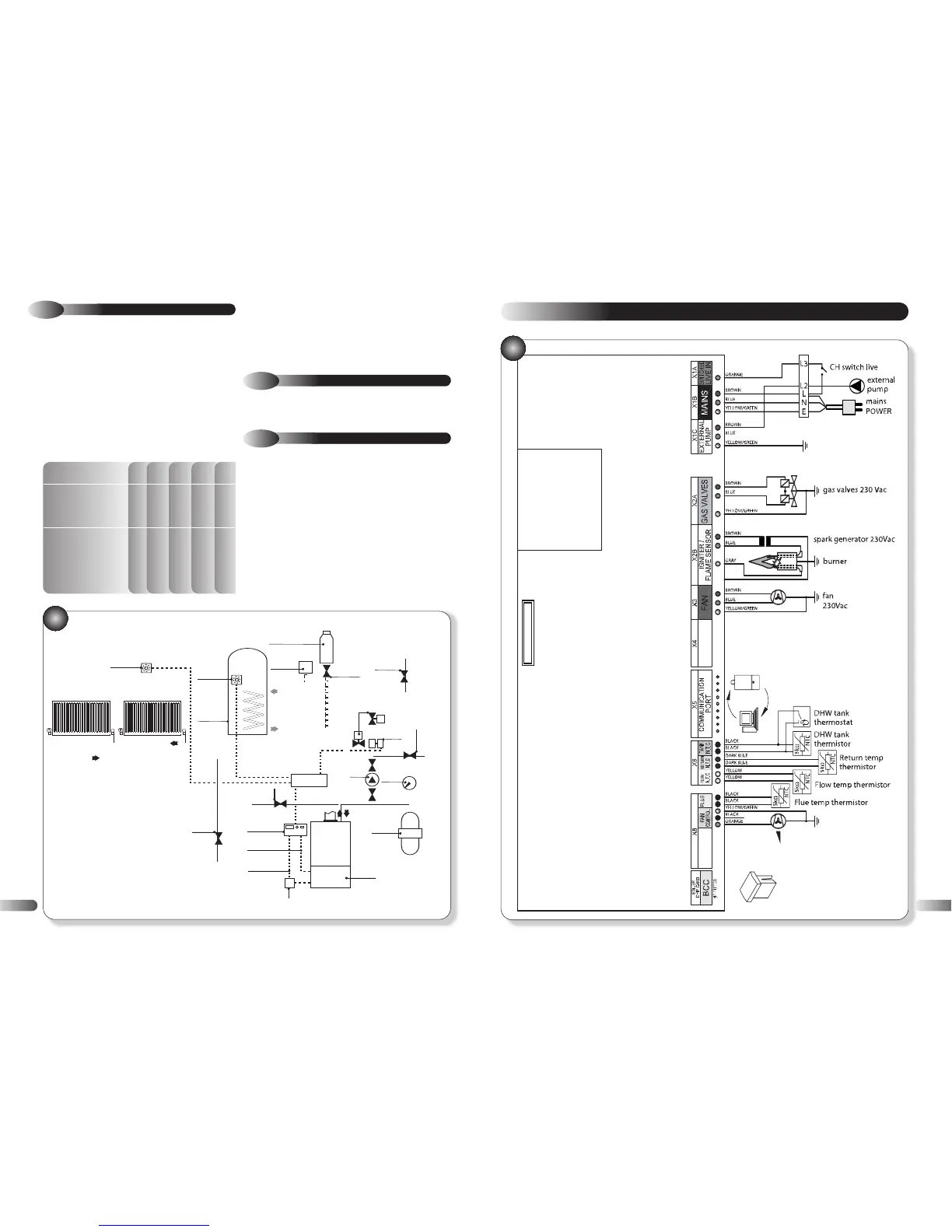
INTERNAL WIRING DIAGRAMS
7
7.1 : FUNCTIONAL FLOW WIRING DIAGRAM
31
25