20
22
FASCIA PANEL AND CONTROLS
(CBX model shown)
23
INLET PRESSURE TEST POINT
5.3
FINAL CHECKS
a) Turn off the appliance and remove the manometer. Tighten the
appliance inlet pressure test point screw. Re-light the burner and
test for gas tightness.
b) Fit the appliance casing as illustrated in Figure 24. Position
and secure both side panels and the decorative front cover with
screws at the top and bottom.
c) Fit the appliance hinged front panel in position with two
screws at the top and bottom.
d) Set the CH Temperature Control to the required setting. Set
the room thermostat (if fitted) to the required setting. Refer to hot
water cylinder instructions.
If the boiler is connected to a hot water cylinder the
CH temperature has to be set to high.
5.4
LOCKOUT / RESET INDICATION
In the event of failure during an ignition sequence, (5 attempts)
the LED displays fault code '3'. In order to reset the boiler turn the
CH Temperature Control anticlockwise to 'STANDBY' position and
then back to 'ON' within
two seconds.
5.5
FROST PROTECTION
The appliance is fitted with a frost protection device. In the event
of very cold conditions, the external pump may operate and the
appliance light for a few minutes to protect the appliance and
system from potential frost damage. This can only function if the
gas and electricity supplies are maintained.
e) Ensure programmer and room thermostat (if fitted) are calling
for heat.
f) The display changes to 'H'. The fan should start and after a
few seconds an ignition will commence.
g) If the burner fails to light the fan will stop. Initially this may be
due to air in the gas supply line. The boiler will automatically
have five attempts at ignition. It may be necessary to turn the CH
Temperature Control knob fully anti-clockwise to reset position and
repeat (d). (See section 5.4).
h) When the boiler has lit the display will show 'H.'. Allow the
appliance to run for at least 10 minutes and check that the gas
supply pressure measured at the appliance inlet pressure test
point is 20 ± 1 mbar for natural gas, and 37 ± 1 mbar for
propane appliances.
5.6
OVERHEAT PROTECTION
The appliance incorporates flow and return thermostats, which
monitor the operating temperature. Abnormal temperatures such
as overheating will cause the appliance to go to lockout and the
LED display will show code '1'. Allow the appliance to cool and
turn the CH Temperature Control knob fully anti-clockwise to the
reset position to clear.
5.7
OTHER FEATURES
The following additional features are included in the appliance
specification:
ANTI-CYCLE DEVICE:
When the appliance cycles on its central heating control
thermostat, a slow cycle device operates. The timer (set to 5
minutes) is activated after the end of each burn cycle to prevent
rapid cycling of the burner.
CH SOFT START DEVICE:
After every burner start the burner output stays at low for 3 minutes,
to ensure smooth heat up of the system and maximum efficiency.
SERVICE MODE:
The appliance enters the SERVICE mode by turning the control
knob fully clockwise. The LED displays a flashing 'H.'. In this
mode the appliance runs at the minimum CH output. This mode
allows the gas valve offset and CO
2
emissions to be measured.
17
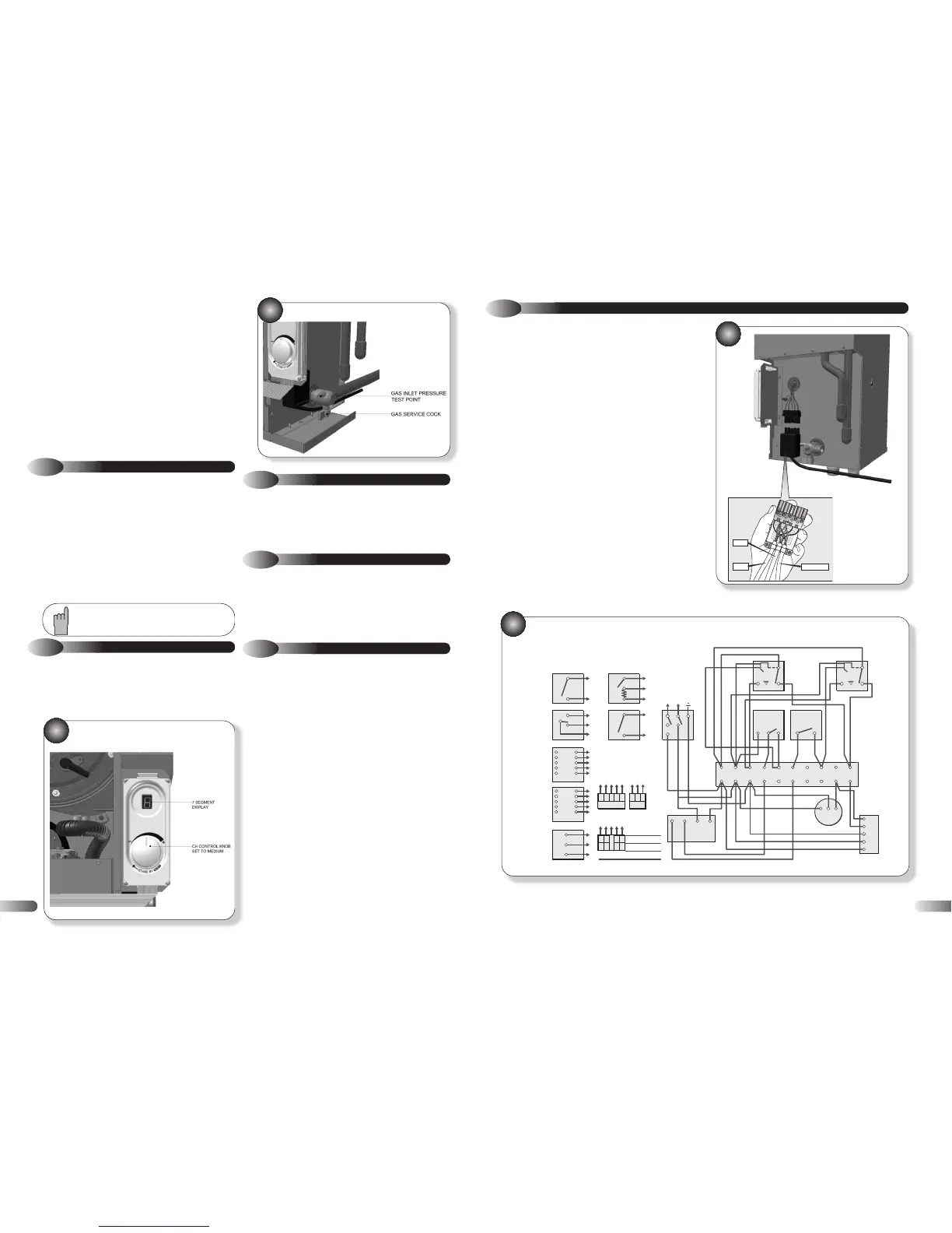
4.8
ELECTRICAL CONNECTIONS
Connect the electricity supply and external controls (using suitable
mains cable) as follows:
Wire the cable(s) into the appropriate connections in the electrical
plug provided, referring to Figure 15. Live supply to L1, Neutral
and Earth as indicated. Check that L1 and L3 are linked.
To provide correct cable retention, fit the piece of tubing supplied
over the cable as it passes through the clamping arrangement.
The cable will be held in position as the plug cover is fitted.
If a programmer/room thermostat is to be fitted remove the red
link between L1 and L3 and connect the device across these
terminals. Any external controls fitted must be rated at 230V
50Hz and have volt free contacts.
15
If using 6-wire 28mm or 1” BSPV4043H on any circuit, white is not
needed and must be made electrically safe. The wiring shown is based
on the use of 10-way junction box (Honeywell Part No. 42002116-001).
Junction Box terminal 10 is switched live and terminal 9 is pump live.
CT200
ROOM
THERMOSTAT
L641A
CYLINDER
THERMOSTAT
V4043H
HEATING
VALV E
V4043H
HOT WATER
VALV E
230V mains
input
16