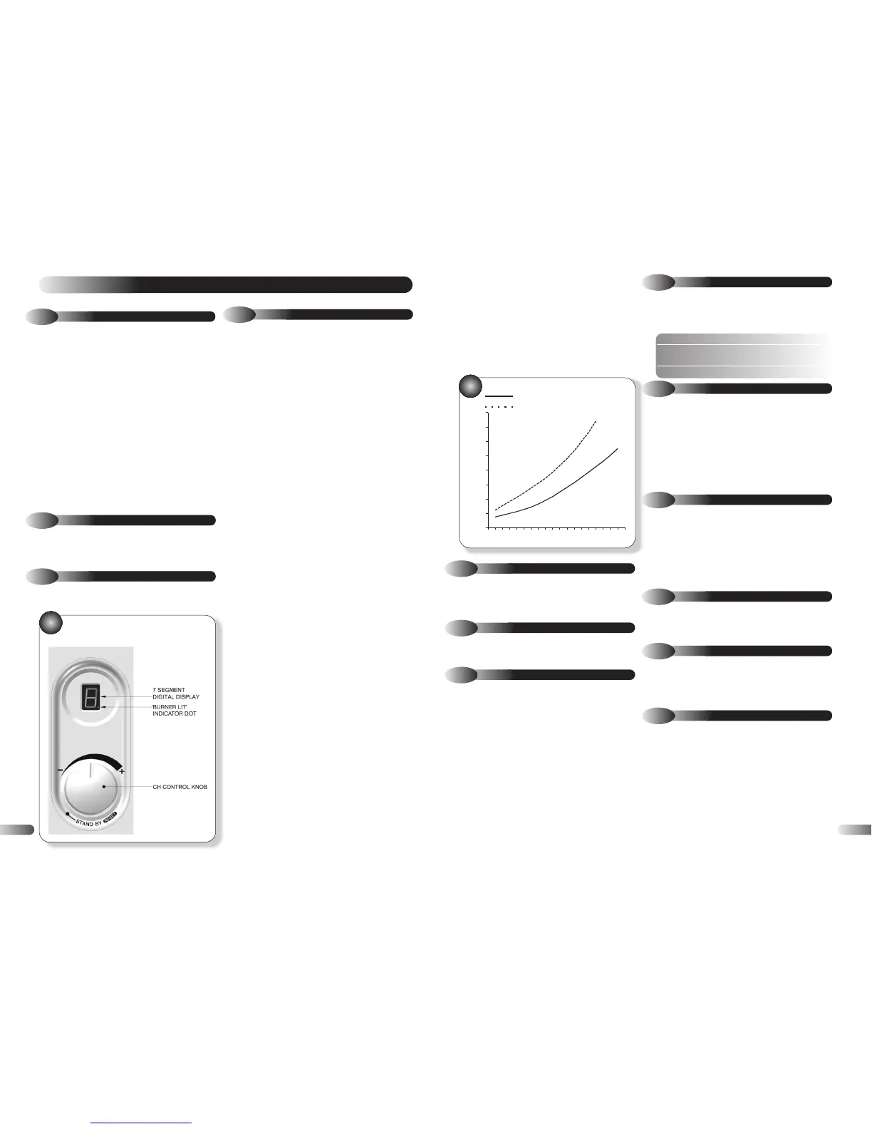
Flow Rate ltr/min
Pressure Drop (m H
2
0)
VBX 30
VBX 18
6
A draining tap must be provided at the lowest point of the system,
which will allow the entire system and hot water system to be drained.
Draining taps shall be to the current issue of BS 2879.
3.8
DRAINING TAP
A safety valve need not be fitted to an open vented system. (See
3.16 for sealed systems)
3.8
SAFETY VALVE OPEN VENTED SYSTEM
3.10
PUMP
The pump should be fitted on the flow pipe from the boiler and
have isolating valves each side.
A variable duty pump should be set to give a temperature
difference of no greater than 20°C between the flow and return,
with the thermostat set at “MAX”, which is approximately 80° to
give a flow rate as shown in table 1.
See figure 6 for pressure loss of the boiler.
High resistance microbore systems may require a higher duty pump.
3.11
FLOW RATE
If it is necessary to alter the flow rate, the system can be fitted
with a lockable balancing valve in the main flow or return pipes
shown as valve “A” in figure 7. The flow rate through the boiler
must not be allowed to fall below that given in table 1.
Table 1. Flow Rate
MINIMUM FLOW RATE
200 l/h
This is equal to 20°C differential at minimum heat input.
3.12
WATER TREATMENT
WATER TREATMENT, CLEANSING AND FLUSHING THE
HEATING SYSTEM
NOTE:
British Standard BS7593: 1992 stresses the importance
of cleansing and flushing of the system to ensure it continues to
run efficiently with the minimum of maintenance necessary.
Halstead Boilers fully support this professional approach and
recommend that the system is cleansed with an effective chemical
cleanser and protected long term with a suitable inhibitor. Such
products are available from Fernox and Sentinal.
3.13
OPEN VENTED WATER SYSTEM
The boiler must be supplied from an unrestricted water supply
taken from a feed and expansion cistern situated at a maximum
height of 27 metres (90ft) above the boiler.
The cold feed must be 15mm minimum size.
The vent must rise continuously and be unrestricted.
It is important that the relative positions of the pump, cold feed
and open vent are as shown in figure 8.
3.14
DOMESTIC HOT WATER CYLINDER
SINGLE FEED INDIRECT CYLINDERS ARE NOT SUITABLE
The domestic hot water cylinder must be of the double feed fully
indirect coil type.
3.15
SEALED WATER SYSTEMS
The installation must comply with the appropriate requirements of
the current issue of BS4814, BS5449, BS6759, BS6798 and
BS7074 Part 1 and 2.
See figure 7 for a suggested layout.
3.16
SAFETY VALVE SEALED SYSTEM
A safety valve must be fitted to a sealed system.
It shall be preset, non-adjustable with a lift pressure of 3 bar,
incorporating seating of a resilient material, a test device and a
connection for drain.
The drain from the safety valve must be routed outside the
building, must not discharge above an entrance or window or
any type of public access area, be clear of any electrical fittings
and positioned so that any discharge can be seen.
26
FAULT FINDING
8
8.1
GENERAL
Before looking for a fault condition, check that:
● The mains electrical supply is turned on.
● The room or cylinder/tank thermostat (where fitted) are calling
for heat.
● The gas service cock is open.
● The system is at design pressure.
Before attempting any electrical fault finding, always conduct the
preliminary electrical system checks as described in the
Instructions for the British Gas Multimeter, or other similar
instrument.
On completion of any service or fault finding operation involving
making or breaking electrical connections, always check for
EARTH CONTINUITY, POLARITY and RESISTANCE TO EARTH.
Detailed procedures for replacing faulty components are
described in section 9 (Parts Replacement).
For further information contact: Halstead Boilers Ltd. Service Help
line: 01926 834834
8.2
DIAGNOSTIC LED INDICATORS
FASCIA PANEL - Refer to Figure 32.
The LED shows code '3' in a lockout condition.
For fault finding refer to the diagnostic chart shown below.
8.3
FAULT FINDING CODES
In the event of the appliance failing to light, refer to the
Diagnostics Chart.
FACIA PANEL
32
Upon a demand for Central Heating, (closure of the time switch
and room thermostat, where fitted), the controls should carry out a
set of start up checks, followed by an ignition sequence. Refer to
Section 5.2.
If the control has powered up correctly but does not respond to a
CH demand. Remove plug cover and check voltage between L3
(orange) and N (blue). If 0 V ac, check external programmer /
room thermostat. If 230 V ac, check control for lockout or
blocking codes, (refer to section 8.3), check operation of the
external pump.
Note: Whenever a CH demand is removed, an anti cycle mode is
initiated which prevents the appliance from firing in CH mode for
5 minutes. Ensure that the control is not in this mode by removing
power from the control and restoring it after a delay of 10
seconds.
If the Switch Live input is OK and no lockout or blocking code
exists and the control is not in anti cycle mode, then replace PCB.
8.4
CENTRAL HEATING FAULT FINDING