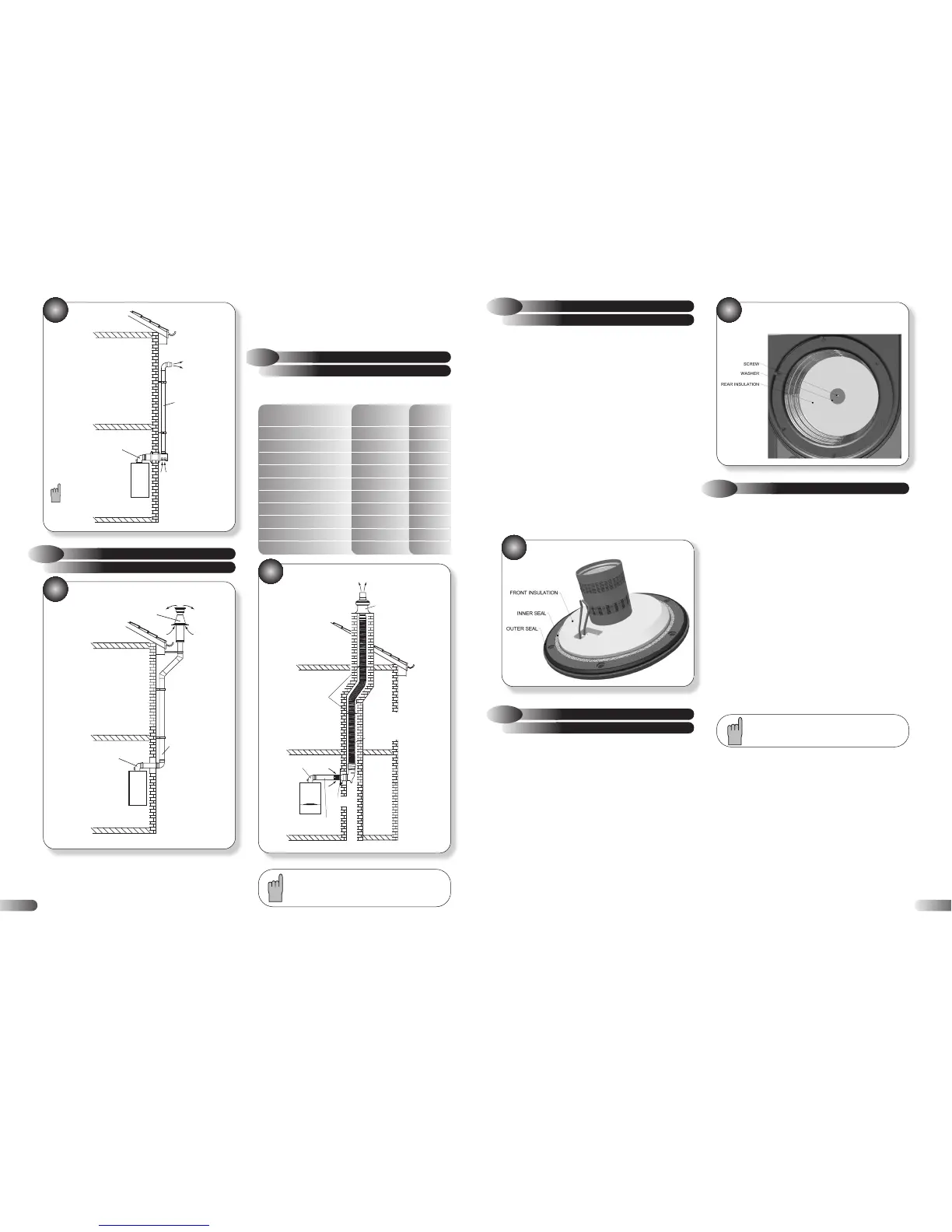
3e
Suitable for installations if the appliance can't be repositioned
and where other horizontal flue options may cause some nuisance
to neighbours or buildings. The flue kit contains some additional
45° elbows and extension ducts as well as a special wall bracket
to pass the guttering (see Figure 3e). The concentric flue will be
2.6
KIT E CHIMNEY FLUE LINER KIT
Maximum flue resistance permitted for an opened flued system = 100 Pa.
Minimum flue resistance permitted for an opened flued system = 38 Pa.
Flue Component Flue Resistance Part
(Pa) Number
Air inlet Assembly (required) 9 -
60/80 Adaptor (required) 12 -
Ter minal (required) 9 -
91.5° Elbow (80) (required) 8 -
80 diameter Corrugated (required) 2/metre -
80 mm diameter straight duct 2/metre -
Horizontal Flue Adaptor 15 956086
Vertical Flue Adaptor 0 956087
93° Elbow (60/100) 15 956091
45° Elbow (60/100) 7 956090
3d
routed vertically alongside the outside wall to above the roofline.
Special seals are required to prevent rainwater penetrating the
pipe joints.
For installation details refer to the flue kit instructions.
31
FRONT INSULATION
9.6
COMBUSTION CHAMBER
The design of the appliance is such that the combustion chamber
insulation should not require replacement unless mechanically
damaged. It is recommended that to prevent dust, the insulation
be dampened prior to removal, and that a protective mask is
worn when changing or handling the insulation material.
Refer to Figure 43
a)
Ensure supply voltage is isolated, and that the gas supply is
isolated.
b) Remove the gas control valve, fan & burner assembly; refer to
section 6.2.
c) Remove the electrodes; refer to section 9.1.
d) Remove the burner: refer to section 9.5.
e) Replace the combustion chamber front insulation.
f) Re-assemble the burner and electrodes, using new gaskets.
g) Check the position of the electrodes: refer to section 6.4.
h) Re-assemble in reverse order; ensure that all joints and seals
are correctly re-fitted.
43
COMBUSTION CHAMBER FRONT
INSULATION
INSULATION
9.7
COMBUSTION CHAMBER REAR
Refer to Figure 44
a)
Ensure supply voltage is isolated, and that the gas supply is
isolated.
b) Remove the gas control valve, fan & burner assembly; refer to
section 6.2.
c) Use an Allen key to undo the central screw holding the rear
insulation in place.
d) Remove old insulation and fit replacement, ensuring locating
washer is in front.
e) Re-assemble in reverse order; ensure that all joints and seals
are correctly re-fitted.
44
COMBUSTION CHAMBER REAR
INSULATION
9.8
HEAT EXCHANGER
Refer to Figures 14, & 45
a)
Ensure supply voltage is isolated, and that the gas supply is
isolated.
b) Remove the gas control valve, fan & burner assembly; refer to
section 6.2.
c) Disconnect the electrical lead to the flue sensor, remove both
flow and return sensors noting which goes where.
d) Drain down central heating system.
e) Disconnect the flue system from the appliance, 4 screws, and
lift up to disengage the flue from the flue hood; refer to Figure 14.
f) Remove the retaining clip from the heat exchanger flow outlet;
refer to Figure 45.
g) Gently pull up (or down, depending on installation) to
disengage the flow pipe from the heat exchanger.
h) Remove the retaining clip from the heat exchanger return
inlet.
i) Gently pull up (or down, depending on installation) to
disengage the return pipe from the heat exchanger.
It may be necessary to cut both flow and return
pipes to disengage them from the heat exchanger.
j) Disconnect the condensate drainpipe from the condensate
drainpipe sump adaptor; refer to section 9.18.
k) Unscrew the three nuts holding the heat exchanger to the
back panel; refer to Figure 45.
l) Remove the heat exchanger.
m) Disconnect the condensate drainpipe sump adaptor from the
heat exchanger.
n) Remove the flue hood from the heat exchanger, two screws,
and fit the flue hood onto the new heat exchanger, Check
integrity of the flue hood seals and replace as necessary. Remove
the manual air vent and vent tube from the heat exchanger and fit
onto to new heat exchanger; refer to Figure 45.
o) Fit the condensate drainpipe sump adaptor to the heat
exchanger and flue hood.
p) Re-assemble in reverse order; check integrity of the flow and