1 2
A
DB
C
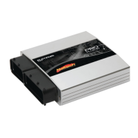
HT400091 HT400090 Standard Harness Connector
Figure 1 - Available Alternator Connectors
Alternator (ALT)
The Alternator output connects directly to the OEM Alternator. The +12V signal and
alternator excite wires are pre-wired into the loom. Both two and four pin versions of
the alternator connector are available.
Camshaft Postition Sensor Input (CAM)
The camshaft position sensor is used in conjunction with the crank angle sensor to
determine crankshaft position and stoke of the engine.
Connector style and wiring of the CAM sensor varies between models therefore two
connectors have been supplied for the end user to terminate for their application.
Some applications connect to the CAM sensor directly whilst others use a small pigtail
harness.
Refer to the table below for correct wiring of your CAM Sensor. Insert pre-rminated
pins into the rear of the connector until they lock.
C
AB
C
A B
Looking into front of connector
Wiring to Pigtail Harness
Location
A
B
C
Wire Color
YELLOW
BLUE
RED
Wiring to Pigtail Harness
Location
A
B
C
Wire Color
YELLOW
BLUE
RED
Blue = GroundRed = 12V Yellow = Signal
Figure 2 - Alternate Cam Sensor Wiring
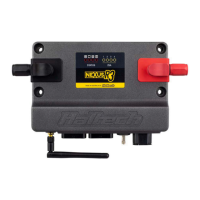
Cabin Wiring
The Cabin Wiring is made up multiple inputs and outputs. Correct connection of these
cables is essential for proper operation of the harness.
All wires have been labeled and required cables should be connected as outlined
bellow.
PINK
VIOLET/BLACK
GREY/BLACK (SHIELDED)
GREY/RED (SHIELDED)
WHITE
GREY
+12V IGNITION INPUT SIGNAL
SPARE DPO OUTPUT
SPARE SPI2 INPUT
SPARE SPI4 INPUT
SIGNAL OUTPUT FOR WBC DIGITAL GAUGE (CH1)
BLACK / WHITE
RED
SIGNAL GROUND FOR WBC DIGITAL GAUGE
+12V FOR WBC DIGITAL GAUGE
ORANGE/BLUE
ORANGE/GREY
+12V OUTPUT FOR FUEL PUMP FROM RELAY
+12V TO STARTER SOLENOID
SIGNAL OUTPUT FOR WBC DIGITAL GAUGE (CH2)
ORANGE/BLACK
SPARE AVI INPUT
Figure 5 - Cabin Harness Wiring