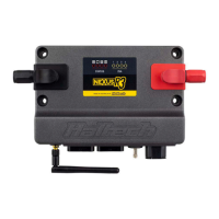
Fuse Box
The Haltech fuse box is connected to the harness. Contained within the Haltech Fuse
box is 6 fuses and 6 relays, each fuse protects the corresponding relay output (ie. fuse
#1 protects relay output #1, fuse #2 protects relay output #2, etc.).
The Haltech fuse box can handle a maximum continuous current draw of 70AMP,
exceeding this value may cause damage to the fuse box therefore please ensure all
auxiliary devices, fans and fuel pumps connected do not exceed the supplied fuse
current limits.
The functions of each of the relays are outlined below:
R1 R2 R3 R4
R5 R6
F1 F2 F3 F4 F5 F6
10
20
15
20
10
Figure 3 - Haltech Fuse Box Relay Allocation Table
Figure 4 - Haltech Fuse Box Layout
Crank Angle Sensor (CRANK)
The Crank signal connects directly to the engine Crank Angle Sensor located in
the right rear of the engine block behind the starter motor.
The Haltech ECU uses this signal to accurately measure crankshaft position and
engine speed.
Ignition 1-8 (IGN1, IGN2, IGN3, IGN4, IGN5, IGN6, IGN7, IGN8)
The ignition outputs connect directly to the factory ignition harness. Ensure the correct
ignition output is connected to the corresponding coil bank on the engine.
Please refer to the label on the harness for correct cylinder bank allocation.
Injection 1-8 (INJ1, INJ2, INJ3, INJ4, INJ5, INJ6, INJ7, INJ8)
The injector outputs connect directly to the injectors. Please ensure the correct
injector output is connected to the corresponding injector in the engine.
Please refer to the label on the harness for correct injector allocation.
Knock Sensors (Knock 1 , Knock 2)
The knock sensor inputs connect directly to the OEM knock sensors. This signal is
used by the ECU Knock Control function to detect knock events within the engine.
Manifold Absolute Pressure Sensor (MAP)
The Manifold Absolute Pressure Sensor is located on the intake manifold.
Connect the MAP labeled connector directly to the sensor.
The MAP sensor measures changes in the intake manifold pressure which result from
engine load and RPM changes and converts these into a voltage output so the ECU
knows the manifold pressure.
Vehicle Speed Sensor Input (VSS-Input) (optional)
The Vehicle speed sensor provides information on vehicle speed to the Haltech ECU
which can be used to display vehicle speed, detect gears or controlling of switches etc.
Connections on the plug are as follows
Pin# 1: Blk/Wht – Sensor Ground
Pin# 2: Gry/Red - +12V Sensor Power
Pin# 3: Grey (Shielded) – Sensor Signal (SPI 1)
Discover other performance engine management systems on our website.