Engine Coolant Temperature Sensor (ECT)
The Engine Coolant Temperature Sensor input connects directly to the OEM engine
coolant temperature sensor located towards front of the head of the left bank.
The Engine Coolant Temperature Sensor provides the ECU with a signal that allows
the ECU to know the current engine temperature.
Intake Air Temperature Sensor (IAT)
The Intake Air Temperature Sensor input connects to a temperature sensor located in
the intake air stream.
The Intake Air Temperature Sensor provides the ECU with a signal that allows the
ECU to know the current intake air temperature.
Ground (GND)
The Ground cable connects directly to the engine block.
this in the earth cable for the engine, please ensure that you earth the
engine with an earth strap from the block of the engine to the chassis of the car.
Ensure that the chassis of the car is connected to the battery negative (-) terminal with
heavy gauge cable or earthing strap.
Damage to the ECU and or terminated harness may result if this is not done.
Wideband O2 Inputs (Wideband Controller, O2-1, O2-2)
Wideband O2 sensors accurately measure the Air/Fuel ratio of the engine which is
required for precise tuning and control of the engine.
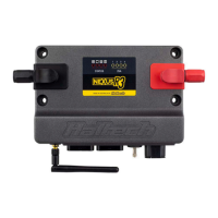
The Terminated harness has been integrated with the Haltech WBC2 wiring harness
allowing a quick installation of a Haltech WBC2 and Wideband O2 Sensors.
Connect your optional Haltech wideband sensors (HT010714) directly to the supplied
connectors labeled O2 in the engine bay. Mount the sensors in the exhaust manifolds.
Connect the Haltech WBC2 to the allocated corresponding connector located near the
main ECU connectors labeled O2,
Connect the Haltech WBC2 to the Haltech Elite ECU directly via the supplied CAN
Cable.
Enable the Haltech WBC2 in your map using ECU manager software.
Your Haltech ECU will now have access to correct Air /Fuel Ratio readings allowing
precise tuning and control of your engine.
Warning NOT
Starter Signal (STS)
The Starter Signal connects directly to the starter motor solenoid. This will supply 12V
to the solenoid on receiving a start signal from the ignition switch when in the start
position.
Please ensure you supply a main power connection to the starter motor and a
main earth strap to the engine to ensure correct operation of the starter motor,
and to avoid damage to your terminated harness and ECU.
Spare Digital Pulsed Outputs (DPO 1, DPO 2 , DPO 4)
The Spare DPO's connector contains one Digital Pulsed Output and one +12V DC
Switched Power.
When the output is activated by the ECU the output will switch to ground. Solenoid
valves and shift lights etc can be run directly from the output, however high current
devices such as thermo fans and additional fuel pumps must be activated through a
relay. A Relay can be wired between the DPO and the supplied +12V DC on this
connector. This way the output is only switching the relay and not a high current draw
device.
The Digital Pulsed Outputs are limited to 800mA Max current draw.
These outputs can be programmed within the ESP Software to control auxiliaries such
as:
• Air Con Output
• Aux Fuel Pump
• Boost Control
• ECU Diagnostic Light
• Intercooler Fan
• Shift Light
• Thermo fans
• Reverse Lockout Solenoid Valve
For a full list of output options and explanations please go to the help within the ESP
Software.