43
Subject to change without notice
If the output is switched on (LED lit) a 48 MHz signal with a
level of approx. –30dBm is additionally connected to the test
signal output. Please note „Test Signal Display“!
TRACKING GENERATOR
N-socket and OUTPUT pushbutton with ON LED. – For
protection of devices connected to the tracking generator
it is always in off condition after switching the instrument
on. This state is indicated by the letter „t“ displayed by the
readout and the LED is not lit. Depressing the pushbutton
switches the tracking generator on, the LED lights, and the
readout now displays the capital letter „T“ in front of the
tracking generator level. Depressing the pushbutton once
again switches the tracking generator off.
A sine wave output signal is provided at the N socket with a
source impedance of 50 Ohm. The sine wave signal frequency
is always identical to the spectrum analyzer receiving fre-
quency.
PROBE POWER
The jack has a diameter of 2.5mm and may be used only for
supply of HZ530 near fi eld probes. The inner connector (+6V)
and outer connector (galvanically connected with Protective
Earth) can supply a maximum current of 100mA.
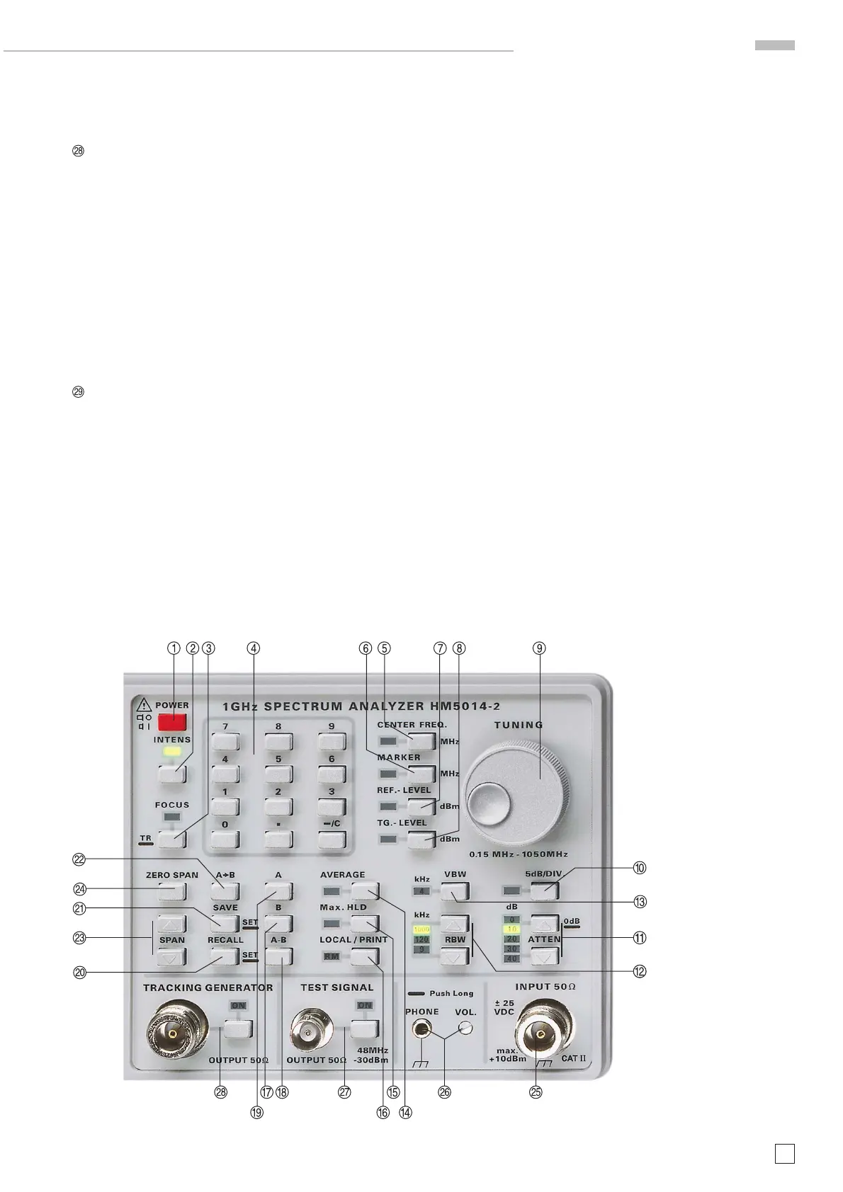
Controls and readout
 Loading...