7
HAMPTONBAY.COM
Please contact 1-855-HD-HAMPTON for further assistance.
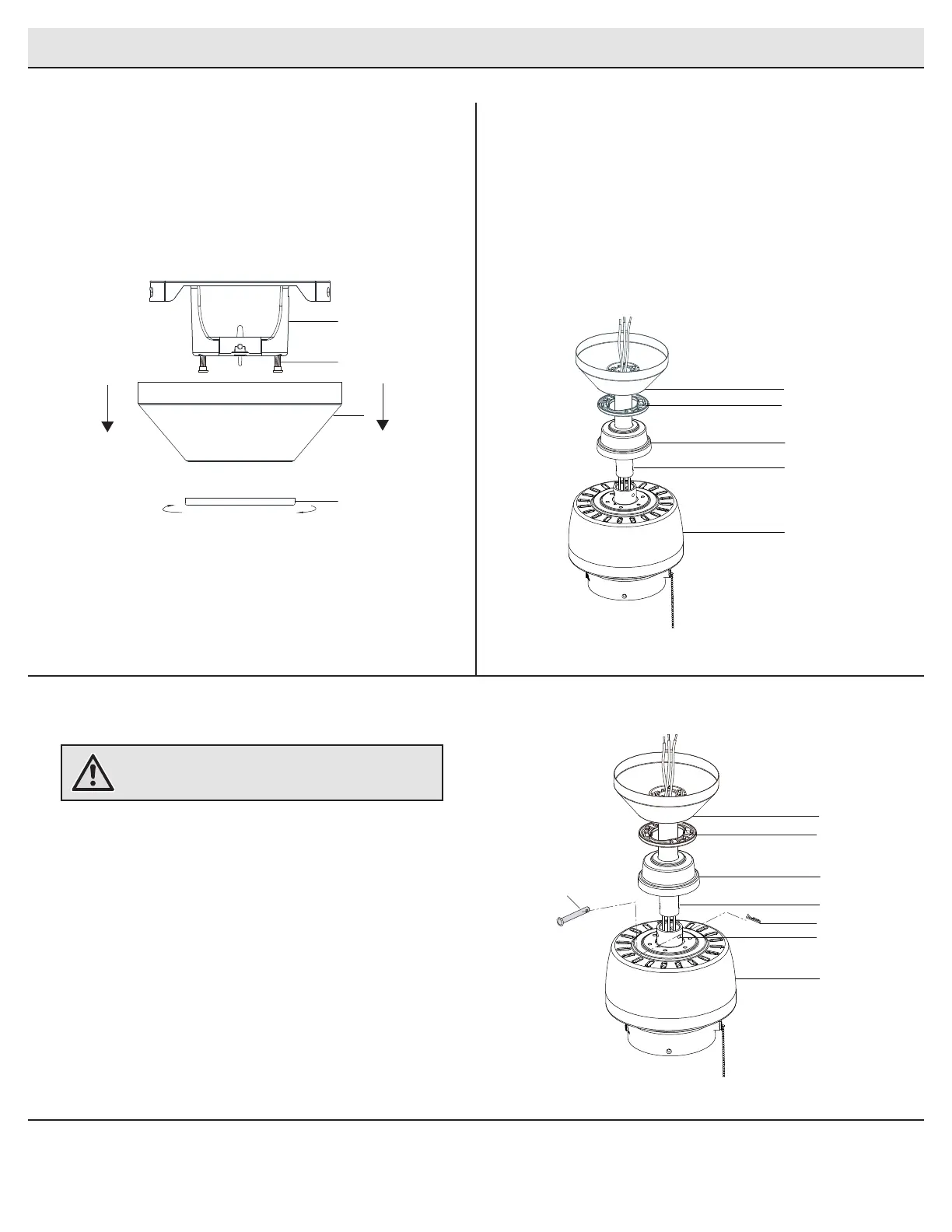
Assembly - Standard Ceiling Mount
Routing the wires
Assembling the fan
Preparing for standard mounting
□ Loosen, but do not remove, the setscrews (JJ) on the collar
on top of the fan-motor assembly (E).
□ Align the holes at the bottom of the ball/downrod assembly
(B) with the holes in the collar on top of the fan-motor
assembly (E).
□ Carefully insert the hanger pin (CC) through the holes in
the collar and ball/downrod assembly (B). Be careful not to
jam the hanger pin (CC) against the wiring inside the ball/
downrod assembly (B).
□ Insert the locking pin (DD) through the hole near the end of
the hanger pin (CC) until it snaps into its locked position.
□ Re-tighten the setscrews (JJ) on the collar on top of the fan-
motor assembly (E).
□ Remove the canopy cover (HH) from the canopy (C) by turning
the bottom cover (HH) counter-clockwise until it unlocks.
□ Loosen the two canopy screws (II) located in the bottom of the
mounting bracket (A), and turn the canopy counter-clockwise
to remove the mounting bracket (A) from the canopy (C).
□ Route the wires exiting the top of the fan motor
assembly (E) through the decorative motor collar cover
(D) and then the center of the canopy bottom cover (HH).
□ Make sure the opening of the canopy (C) is on top and
insert the ball/downrod (B) through the canopy (C).
□ Route the wires exiting the top of the fan motor
assembly (E) through the downrod as shown.
2
3
1
WARNING: Failure to properly install the locking pin (DD)
could result in the fan becoming loose and possibly
falling.
C
A
II
HH
C
D
E
B
HH
C
D
E
B
HH
CC
DD
JJ