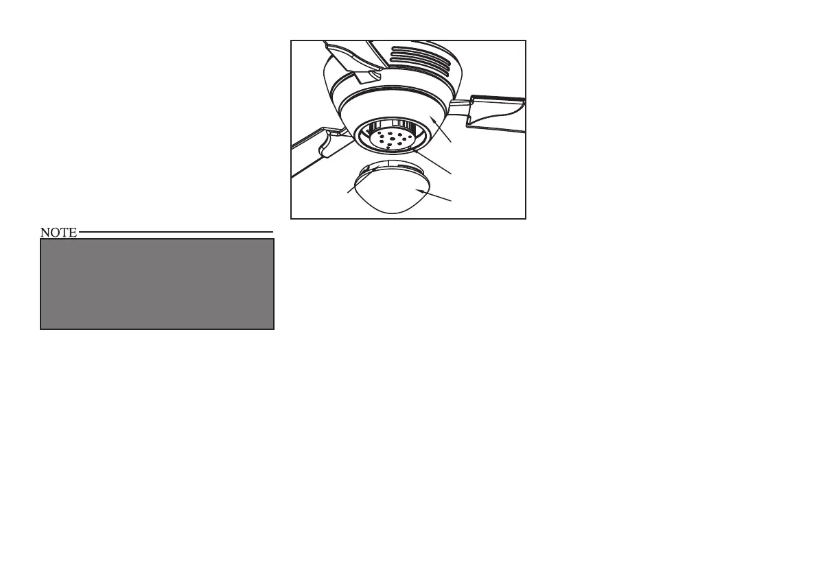
2. Connect the red and white wires from the
fan motor assembly with the red and white
wires from the lower housing by engaging
the 1-positioned connectors (Figure 16).
3. Position the lower housing onto the black
bracket of the fan motor assembly, align-
ing each of the four holes. Rotate the low-
er housing clockwise to engage the three
mounting screws and lockwashers with the
three key hole slots, tighten the screws. Re-
install the one mounting screw that were re-
moved in step 1 and tighten rmly.
4. Place the glass into the lower housing, align-
ing the three at areas on the top ange of
the glass with the three raised dimples in the
lower housing. Turn the glass clockwise un-
til it stops (Figure 17).
9.
Lower Housing
Glass
Flat Area
Raised Dimples
Figure 17
NOTE: PERIODICALLY CHECK THE
GLASS SHADE IS SEATED FULLY CLOCK-
WISE IN THE LOWER HOUSING.
THE LIGHT SOURCE IS DESIGNED FOR THIS
SPECIFIC APPLICATION AND CAN OVERHEAT
IF SERVICED BY UNTRAINED PERSONNEL. IF
ANY SERVICING IS REQUIRED, THE PRODUCT
SHOULD BE RETURNED TO AN AUTHORIZED
SERVICE FACILITY FOR EXAMINATION OR
REPAIR.