HAMWORTHY HEATING LTD
45
FLEET V series
500001213/G
BMS Connections
For 0 - 10v connection, the input signal must be connected to terminals 15 & 16 - see figure 4.6
Note: any safety interlocks MUST be wired across the 0– 10v circuit using suitable low voltage contact ratings.
For connection of an external alarm device, use terminals 8 & 9, which are volt free and rated at 230v - see figure
4.6
For an optional programmable room thermostat, use connector X10-01 on the LMU - see figure B.1.3
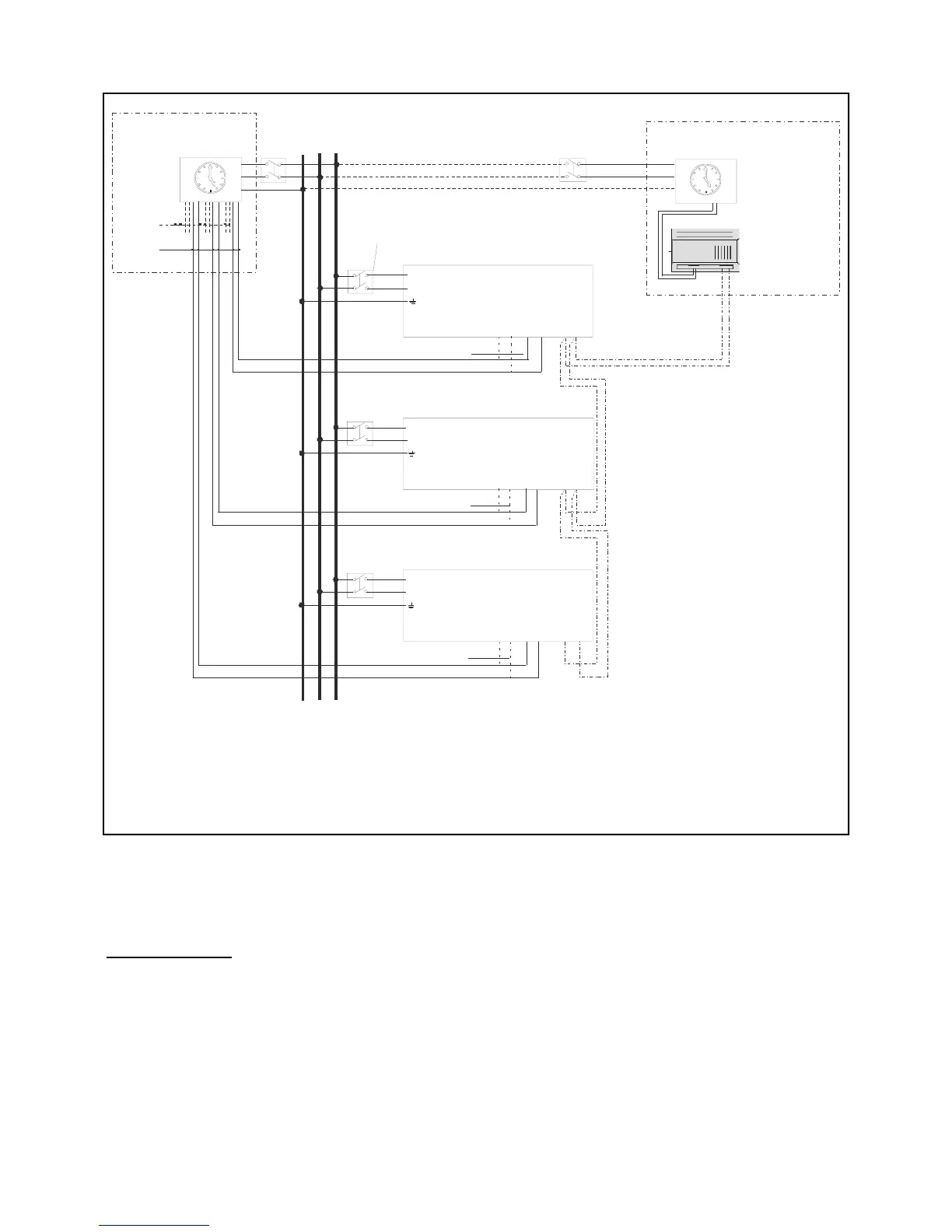
Figure B1.2 - External Control Wiring for Multiple Module Installation
LNE
3
3
3
2
2
1
1
2
1
13 14
13 14
13 14
21 22
21 22
21 22
15 16
15 16
15 16
External
Control
Optional
External
Control
Boiler 1
Terminal Rail
Boiler 2
Terminal Rail
Boiler 3
Terminal Rail
0~10V
0~10V
0~10V
Control
Signal
0~10V
or
Enable
Note:- each module requires independent isolation of electrical supply and control signals.
Signal cables must not be run in the same conduit as mains voltage cables
Option 1 - reference should be made to Building Regulations and CIBSE Guide ‘Energy Eff iciency in Buildings’ for controls requirements.
All modules must be sequenced.
Enable - will give On/Off control of the modules
0~10V - will give modulation control of each module
Option 2 provides modulation control of up to 16 modules.
Local Isolator
Option 1 Remote Control
Option 2 Merley Cascade Control
LPB
Bus
Control Signal
0-10V or enable