HAMWORTHY HEATING LTD
11
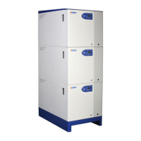
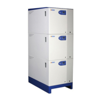
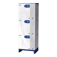
FLEET W series
500001211/F
4.3 Flue System
The Fleet flue systems supplied by Hamworthy are non UV stabilised polypropylene and
are therefore suitable for internal use only. For external flue runs and termination, either
use the dedicated kits supplied by Hamworthy or refer to a chimney specialist .
Flue termination, routing and construction must comply with the requirements of the
Clean Air Act 1956, BS 6644, BS 5440 and IGE/UP/10 where applicable.
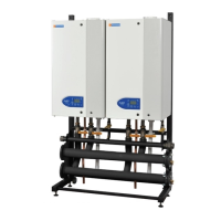
Fleet boilers installed in modular format with a common flue, must use the header
provided with the boiler prior to any connection to the flue system. Individual modules
must be flued using the concentric or twin duct systems provided .
Fleet boilers are suitable for open flue (type B
23
) installation, drawing combustion air
from the plant room, or room sealed, twin duct (type C
53
) installation - see section 5.2.
For type B
23
installations, the maximum number of modules firing into a common
chimney is 9. For larger installations refer to HHL Technical.
The flue system must be designed to limit the max. suction (cold) to 30Pa negative,
measured at the connection to the boiler. If the suction is greater than 30Pa, refer to HHL
technical. This condition must then be checked hot and with all boilers firing, the max.
pressure at the connection to the boiler should be 150Pa positive. In the event that the
flue when hot does generate a suction, the max. suction is 100Pa.
For type B
23
installations the boiler connection kit provides a filtered air inlet and MUST
be used at all times. Refer to appendix C.
Any stabiliser fitted must be in or close to the vertical chimney.
Due to the low flue gas temperature, (~50°C) condensation will occur in the flue, flue
materials must be non-corrosive and utilise fully sealing joints.
Adequate facilities must be provided for draining the flue condensation from the flue
system using the components available from HHL - refer to Appendix C. For short flue
runs (<1m) it is not practical to provide drainage from the flue system.
Horizontal runs of flue must provide condense drainage from the flue /chimney and must
slope at 3° (50mm/m) along the horizontal length, towards the boiler. For longer flue
systems (>1m), the flue system MUST NOT drain through the boiler - see section 5.2 .
For multiple boilers into a common flue header, the common header must slope at 3°
back to the boilers and provision made to remove condensate from the header - see
section 5.2 .
Horizontal flue runs must be kept as short as possible and be inclined at minimum 3°
(50mm/m) towards the boiler. For maximum equivalent flue lengths, refer to Appendix C.
Any flue must be self-supporting and separable from the boiler for servicing
requirements.
Note: Due to high thermal efficiency of the Fleet boiler and the resultant low flue gas
temperatures there will be visible pluming of the flue gases at the flue termination. This
is likely even when the boiler is not operating at condensing temperatures.
Fan dilution - the design must provide for the use of balancing and trim dampers,
and their location and operation must be such that the constraints detailed above
can be met. Care must be taken to ensure that the fan performance is matched to
deliver the appropriate dilution, whilst ensuring that excessive suction is not
applied to the boilers. If in doubt, refer to HHL Technical.
 Loading...