CROSS CONVEYOR
ADJUSTMENT
Proper tension should be maintained on cross con-
veyor chain when operating box. To adjust cross
conveyor, loosen the jam nuts (A) on tightener
bolts (B). Move adjusting nuts (C) on tightener
bolts until proper tension on chain is reached. The
chain is properly adjusted when the center slats
clear the bottom return pan by about 1/16 of an
inch. Adjust both sides equally. Lock in place with
jam nuts.
SHEAR BOLT
The cross conveyor is protected by two shear
bolts, located in the drive sprocket and shear hub
assembly, located at the right hand end of cross
conveyor. Two spare shear bolts are provided.
Always determine the cause of failure and elimi-
nate the cause before installing new shear bolts.
Use only H&S shear bolts, part number RGB38
when replacing shear bolts.
A. Spare Shear Bolts
B. Shear Bolts
-14-
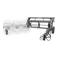
Shown here is the spring loaded plastic guard
which protects the operator from accidentally being
exposed to the bottom beater at the discharge
opening during operation of forage box. Keep this
guard in proper position at all times when operating
forage box.
B A C
ITEM PART NO. DESCRIPTION
1. G90 Dust Cap
2. 3G19 Snap Ring
3. 3G18 Race #15245
4. 3G7 Bearing #15101
5. X9 Spacer
6. G83 Set Screw
7. G76 Worm
8. G114 Gearbox Housing
9. X8 Gearbox Bushing
10. S138 3/8’’ x 2-3/8’’ Square Key w/Round Ends
11. S139 Worm Gear Side Shaft
12. S437 3/8’’ x 1-3/8’’ Square Key w/Round Ends
13. G65 Plug 3/8’’
14. 5B10 1/4’’ x 1’’ Woodruff Key
15. S140 Worm Gear Front Shaft
16. L3G24 Gearbox Bearing #15113
17. G115 Seal
18. G84 Cap Screw
19. X75 Cover Bushing
20. G116 Worm Gearbox Cover
21. G77 Worm Gear
22. G91 Vent Plug
23. G117 Cap
24. G120 Seal 1-7/8’’
* G118 Worm Gearbox Complete
NOTE: * (Means Not Shown)
-47-
FIGURE 9
WORM GEARBOX