TO PREVENT SERIOUS INJURY OR DEATH
NEVER OPERATE THIS UNIT UNLESS EMERGENCY STOP FUNCTIONS PROPERLY
W A R N I N G
-10-
1. Pushing the emergency stop bar rearward or
pulling the trip cables will activate the stop to
disengage position.
2. Activating emergency stop only stops box
functions. The PTO shaft will continue to rotate.
3. Keep excessive slack out of trip cables.
4. Trip emergency stop occasionally, and when
starting the unit after periods of storage to
insure proper function.
5. To reset, move lever (A) clockwise to engage
position.
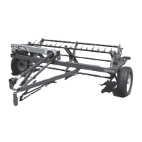
UNLOADING - FRONT UNLOAD
1. Park forage box on level ground whenever
possible during unloading. Lock tractor parking
brake.
2. Connect PTO to tractor, locking securely in
place. USE 540 PTO ONLY.
3. Engage PTO.
4.To engage cross conveyor INTERMITTENTLY,
rotate clutch lever (A) clockwise and hold with
hand pressure. If hand pressure is removed,
the cross conveyor will stop.
5.To engage the cross conveyor CONTINUOUSLY,
rotate clutch lever (A) clockwise until it locks in
the engaged position. Cross conveyor speed is
controlled by tractor RPM only.
A B
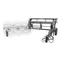
6. Quickly engaging/disengaging beaters (lever B) will allow beaters to clear material a little at a time to
avoid exceeding blower capacity.
7. When beaters are clear of material, move control lever (B) to apron speed positions. Variable speed
drive offers you a number of unloading speeds to choose from. With experience and depending on the
type of forage, you will be able to select a speed which will match your blower capacity.
Unloading speed may also be varied by increasing or decreasing engine speed of tractor.
PIN MUST BE IN END OF
DESIRED UNLOADING ONLY.
INSERT PIN UNTIL FLUSH.
TURN CLOCKWISE UNTIL LOCKED.
INSERT QUICK PIN TO
LOCK IN POSITION.
31300
FIGURE 12
CROSS CONVEYOR CLUTCH - BELT DRIVE
-51-
ITEM PART NO. DESCRIPTION
2. S335 Front Clutch Plate
3. S341 Idler-Stop Assembly
4. S337 Handle Lever
5. S332 Drive Belt Set
6. S342 Pulley
7. S339 Handle Mount
8. S343 Shifting Rod
9. 11S19 Sprocket 50B20
10. S340 Tightener Pivot Shaft
11. S338 Handle Lever
12. 4C7 Bearing Flange
13. X85 Bearing Flange Sheared
14. K156 Idler Pulley
15. S458 Input Pulley Shaft
16. 4C8 Bearing
17. S347 Shifter Rod End
18. 23N211 Spring 5/8’’
19. X111 3/8’’ x 1’’ Bolt GR.5
20. BFR320 3/8’’ x 1-3/4’’ Bolt GR.2
21. S352 Internal Star Washer
22. K60 3/8’’ Nut
23. B68 3/8’’ Lockwasher
24. S355 3/8’’ Jam Nut
25. K25 3/8’’ Locknut
26. 16SV91 1/2’’ x 3-1/4’’ Bolt GR.5
27. R11 1/2’’ Top Locknut
28. 5B10 1/4’’ x 1’’ Woodruff Key
29. --- 3/8’’ Setscrew
30. --- 5/16’’ Setscrew
31. A14 3/8’’ Nylock Nut
32. X67 3/8’’ Flatwasher
33. S344 Clutch Rod Slide
34. S348 Spring Bracket
35. S349 Drive Pulley Shaft
36. S438 Clip Pin
37. 4C9 Bearing Lock Collar
38. S345 Spacer (.074) (As Needed)
39. K99 Spacer, 7/8’’
40. BFR335 5/16’’ x 2’’ Expansion Pin
41. K68 1/2’’ Flat Washer
Spacer, 9/16’’
Spacer, 1/2’’
Cable Clamp
Thimble
42. 23N94
43. K106
44. BFR220
45. ES4
46. ES5
Cable Compression Sleeve
47. S361 Stop Cable Stiffener
48. S358 Emergency Stop Cable
49. S362 Handle Lever Grip
50. S369 Spring, 3/4’’
51. ES7 Hair Pin
52. R35 1/2” Lock Washer (As Needed)
53. S135 1/4” x 1-1/4” Square Key