6 Mini Maxx Installation Manual • www.hsperformance.com
PARTS DESCRIPTION
This section describes each of the parts in the Bill of Materials, the descriptions provide a physical set of
attributes and a purpose for each part. The parts descriptions also list everything that is included in each
assembly.
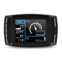
The Mini Maxx Head Unit
The main component is the Mini Maxx Head Unit. The Head
Unit is the interface in which you control vehicle perfor-
mance parameters. It is also the brains that will save vehicle
activity and defuel a vehicle. Notice that the head unit has:
seven total buttons, ve on the left side and two on the right,
a large color screen, and an electronic plug for docking on
the back. Note that this is the last piece that you will install.
Note: Mini Maxx includes a micro SD card inserted
in the side of the Head Unit.
Power Cable
The Power cable connects the OBD ll Adaptor Plug to the ve-
hicle fuse box to supply power to the Mini Maxx. It is optional
to use as there are two ways to power up your Mini Maxx
1. (Recommended) Use this power cable and wire it to the
designated location specied later in this manual.
2. The OBD II port provides constant 12V+ power, so your
Mini Maxx can power o of the OBD II port alone. But in
this situation the Mini Maxx will not turn on and o with
the ignition. There is a switch on the OBDII adapter plug
in order to turn the Mini Maxx on and o.
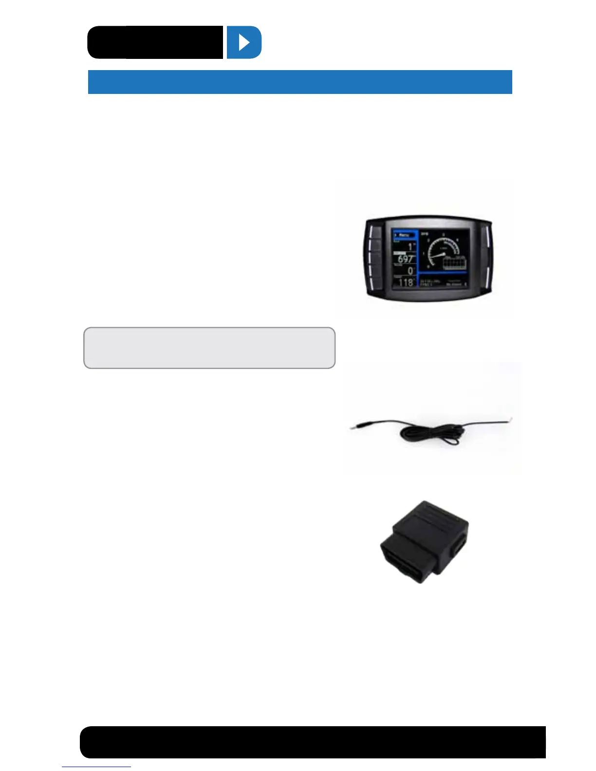
OBDII Adapter Plug
The OBDII Adapter is a communication hub for the Mini Maxx.
The OBD ll Adaptor plugs directly into the vehicle OBD ll port. Notice the OBD ll Adaptor has many ports to
support various other functions of the Mini Maxx.
PARTS DESCRIPTION