14
After the left tower has depressurized, the Left Purge
Valve V3 is opened and the Blower M and Heater
H1 are energized. The heated air flows through the
Left Purge Check Valve V5, down through the left
tower, and exits through the Left Purge Valve V3.
The Blower intake air is filtered to keep dust and dirt
from entering the dryer. The Blower M and Heater
H1 are de-energized when the temperature at the
bottom of the left tower, as sensed by the Left Tower
Temperature Sensor RTD1, reaches the Heat Ter-
mination set point. This indicates that the bed has
been fully heated.
The Repressurization Valve V11 is opened. A portion
of the dry air from the right tower now flows through
Repressurization Valve V11. This air is throttled to
near atmospheric pressure by Repressurization/
Sweep Orifice O1. The dry, low pressure air flows
down through the left tower cooling the desiccant
bed, and exits through the Left Tower Purge Exhaust
Valve V3.
The Cooling Step continues until:
a) the left tower bed temperature falls to 150°F
or,
b) it is time to repressurize the left tower,
whichever occurs first.
Note: In fixed cycle, the bed will normally be partially
cooled because the repressurization step will occur
before the bed temperature can fall to 150°F.
Note: In Energy Management or Dew Point Control,
as the drying time extends beyond 4 hours, additional
cooling time becomes available thus the cooling
step will frequently terminate based on temperature
providing complete bed cooling.
At the end of the Cooling Step, the Left Tower Purge
Exhaust Valve V3 is closed. The left tower slowly
repressurizes to full line pressure and is ready to go
back on-line.
Note: Bed cooling can be disabled by moving JP4
to the “ON” position.
6.3.1 Energy Management Control (optional)
Operation of the Energy Management Control cycle is
identical to the fixed cycle except the cycle is extended
until the desiccant bed in the on-line tower has been fully
utilized. The off-line tower is regenerated and remains
in a stand-by mode after being repressurized.
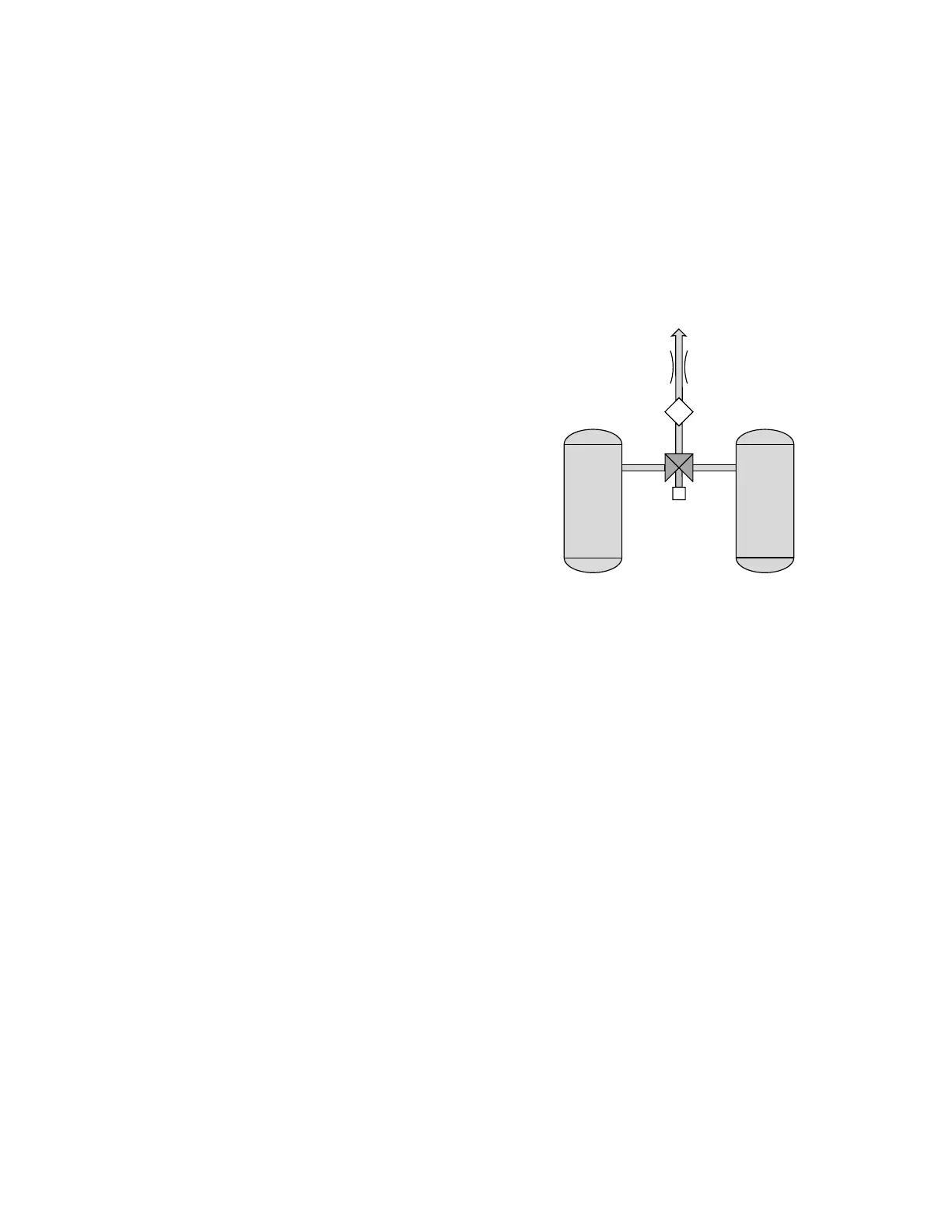
Figure 5 shows the air sampling system for the Energy
Management System – EMS option. A 3-way pilot valve
directs an air sample from the drying tower to the EMS
sensor. The EMS sensor detects the relative humidity
and temperature of the air sample. The air sample then
exhausts to atmosphere. The drying tower remains on-
line until the moisture front arrives at the sensor.
Figure 5
Optional Moisture Sensing
Energy Management System (EMS)
 Loading...