The provided document is an instruction manual for the Hankison HPET Series of High Pressure Refrigerated Compressed Air Dryers with ColdWave™ Technology. The models covered are HPET-4, HPET-6, HPET-7.5, and HPET-10.
Function Description
The Hankison HPET Series dryers are designed to remove moisture from compressed air, providing dry air for various industrial applications. They utilize refrigeration technology to cool the compressed air, causing water vapor to condense into liquid, which is then separated and drained. This process helps prevent issues such as corrosion, equipment damage, and product contamination that can result from wet compressed air. The "ColdWave™ Technology" suggests an advanced or optimized refrigeration process for efficient moisture removal.
Important Technical Specifications
The manual provides detailed engineering data for the HPET-4, HPET-6, HPET-7.5, and HPET-10 models, covering air system data, refrigeration system data, and electrical data.
Air System Data:
- Maximum/Minimum Inlet Air Pressure: 725 psig (50 barg) / 15 psig (1.0 barg). This indicates the dryer's robust design for high-pressure applications.
- Maximum/Minimum Inlet Air Temperature: 120°F (49°C) / 40°F (4°C).
- Maximum/Minimum Ambient Temperature:
- Air-cooled models: 110°F (43°C) / 40°F (4°C).
- Water-cooled models: 130°F (54°C) / 40°F (4°C).
- Outlet Air Temperature (nominal at rated conditions): 85°F (29°C).
Refrigeration System Data:
- Refrigeration Capacity @ Rated Flow (BTU/hr):
- HPET-4: 42,140 (60 Hz), 41,400 (50 Hz)
- HPET-6: 57,310 (60 Hz), 58,000 (50 Hz)
- HPET-7.5: 69,370 (60 Hz), 70,900 (50 Hz)
- HPET-10: 92,550 (60 Hz), 93,300 (50 Hz)
- Refrigerant Type: R-404a.
- Suction Pressure Setting: 78 psig (5.4 barg).
- Compressor Control Ranges (out-in):
- Air-cooled models: High (450-350 psig), Low (84-67 psig)
- Water-cooled models: High (320-280 psig), Low (84-67 psig)
- Condenser Fan Switch Setting (air-cooled models):
- Fan 1: 300-230 psig (21-16 barg)
- Fan 2 (Models 6, 7.5, 10): 325-255 psig (22-18 barg)
- Water Regulating Valve Setting (water-cooled models): 135 psig (9.3 barg).
- Required Available Water Pressure Differential (water-cooled models): 40 psig (2.8 barg) - minimum.
- Flow Required with 85°F Cooling Water (gallons per minute) (water-cooled models):
- HPET-4: 12 (60 Hz), 10 (50 Hz)
- HPET-6: 14 (60 Hz), 12 (50 Hz)
- HPET-7.5: 21 (60 Hz), 18 (50 Hz)
- HPET-10: 27 (60 Hz), 23 (50 Hz)
Electrical Data (for 230/3/60, 460/3/60, 575/3/60, and 380-420/3/50 nominal voltages):
- Input Power @ Rated Flow (watts): Ranges from 3,590 to 14,400 depending on model and frequency.
- Minimum Circuit Ampacity: Ranges from 10.2 to 63.0 amps.
- Maximum Overcurrent Protector (amps): Ranges from 15 to 100 amps.
- Compressor Rated Load Amps: 8.2 to 21.1 amps.
- Compressor Locked Rotor Amps: 49.5 to 127.0 amps.
- Compressor Winding Resistance (ohms): 3.64 to 1.02 ohms.
Rated Capacity (scfm) @ 725 psig inlet pressure, 100°F inlet temperature, 100°F ambient temperature, 60 Hertz operation:
- HPET-4: 1250 scfm (2125 m³/hr)
- HPET-6: 1750 scfm (2975 m³/hr)
- HPET-7.5: 2000 scfm (3400 m³/hr)
- HPET-10: 3000 scfm (5100 m³/hr)
Capacity Adjustment Factors: The manual includes tables for adjusting capacity based on air inlet temperature and pressure, ambient air temperature, and electrical frequency (50 Hz or 60 Hz).
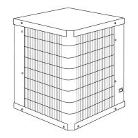
Dimensions/Weights:
- DIM "X" - Cooling Water I/O Connections:
- HPET-4: 3/4-14 NPT (FEMALE)
- HPET-6: 1-14 NPT (FEMALE)
- HPET-7.5 & HPET-10: 1.1/4-11.5 NPT (FEMALE)
- DIM "Y" - Air I/O Connections: 3"-8 NPT (MALE) / Rc 3"-11 BSPT (MALE).
- Weights:
- HPET-4: 889 lbs (404 kg)
- HPET-6: 939 lbs (427 kg)
- HPET-7.5: 1204 lbs (547 kg)
- HPET-10: 1329 lbs (604 kg)
Usage Features
The HPET Series dryers are designed for ease of installation, operation, and monitoring.
Installation:
- Location: Can be placed in a compressed air system after an aftercooler and before a separator and oil removal filter. Requires a minimum of 36 inches (914 mm) clearance for free air flow and maintenance.
- Ambient Conditions: Designed for indoor installation. Air-cooled units operate in 40-110°F (4-43°C) ambients, while water-cooled units operate in 40-130°F (4-54°C) ambients.
- Piping: Inlet and outlet connections are clearly marked. Flexible connections are recommended to prevent vibration damage. Bypass piping is suggested for servicing without interrupting air supply. Water-cooled models require cooling water inlet/outlet connections, and come with a strainer and water regulating valve.
- Electrical: Designed to operate on specific voltage, phase, and frequency as listed on the serial tag. The refrigeration condensing unit should run continuously and not cycle on/off with the air compressor.
- Moisture Separator: Features an external drain that automatically discharges collected condensate. A three-way valve assembly is installed for manual draining and drain valve maintenance.
Operation:
- Start-up Procedure:
- Confirm On/Off Switch is in "Off" position.
- Check for proper electrical voltage.
- Energize dryer disconnect switch 24 hours before starting the refrigeration compressor (crucial for compressor longevity).
- For water-cooled models, begin cooling water flow after 24 hours.
- Toggle ON/OFF switch to "ON" position; green power-on light illuminates.
- Slowly pressurize the unit air side by opening the inlet isolation valve and check for leaks.
- After 15 minutes, open the outlet isolation valve slowly.
- Close the air by-pass valve.
- Control Panel: Includes an On/Off Switch, Power On Light, Compressor On Light, Dew Point Temperature Indicator, and a Drain Push-to-Test button.
- Timer Drain: Features a pre-programmed timer drain with adjustable intervals via the "Drain Interval Program" and "Drain Interval Selector" buttons. The Dew Point Temperature Indicator LEDs correspond to different drain cycle settings. The drain open time is fixed at one second.
- Safety: Warnings are provided for pressurized devices (do not exceed max operating pressure, depressurize before service), electrical hazards (install per codes, disconnect power before service), and breathing air (may require further purification).
Maintenance Features
The manual outlines routine maintenance procedures to ensure optimal performance and longevity of the dryer.
Condenser Coil:
- Air-cooled: Clean accumulated dust and dirt monthly or as necessary.
- Water-cooled: Clean strainer monthly, or more often if required. This involves shutting off water, removing plugs, and cleaning the strainer.
Moisture Separator/Oil Removal Filter:
- Element Replacement: Replace filter element annually or when excessive pressure drop occurs. Maintenance kits are available with all necessary components.
- Procedure for Separator/Filter Element Replacement:
- Isolate dryer or shut off air supply.
- Remove front panel and depressurize filter via manual drain by-pass valve.
- Disconnect drain line.
- Disassemble filter housing (unscrew bowl by hand or strap wrench).
- Clean filter bowl.
- Remove and replace complete element (discard old element and small O-ring).
- Install new filter element and bowl with new O-rings.
- Connect drain line and replace panel.
- Repressurize dryer and resume operation.
Drain Mechanism:
- Daily Check: Ensure automatic drain is discharging.
- Weekly Blow Down: Push the test button on the control panel.
- Annual Rebuild: Rebuild the drain mechanism annually; maintenance kits are available.
Troubleshooting Guide: A comprehensive guide is provided to diagnose and resolve common issues, including water downstream of the dryer, high pressure drop, high temperature alarm, and refrigeration system malfunction. It suggests possible causes and corrective actions, such as checking valve positions, cleaning components, resetting drain timers, and contacting qualified refrigeration repairmen.
Parts List: A detailed list of replacement parts is provided for each model (HPET-4, HPET-6, HPET-7.5, HPET-10), including compressor, fan motor, fan blade, crankcase heater, various pressure switches, valves, filter dryer, temperature sensor, contactors, transformer, fuses, and control board components.
Maintenance Kits: Specific maintenance kits (HPETMK10, HPETMK11, HPETMK12) are listed for each model, which include elements, drain rebuild kits, bowl O-rings, and water valve strainer screens.
Warranty: The manufacturer provides a warranty covering defects in material or workmanship for two (2) years for parts and labor, and an additional three (3) years (total of five [5]) for heat exchangers (parts only). It emphasizes that unauthorized service voids the warranty and that authorization from the service department is required for returns or in-warranty repairs.