3
IMPORTANT: READ PRIOR TO STARTING THIS EQUIPMENT
1.0 INSTALLATION
1.1 Location
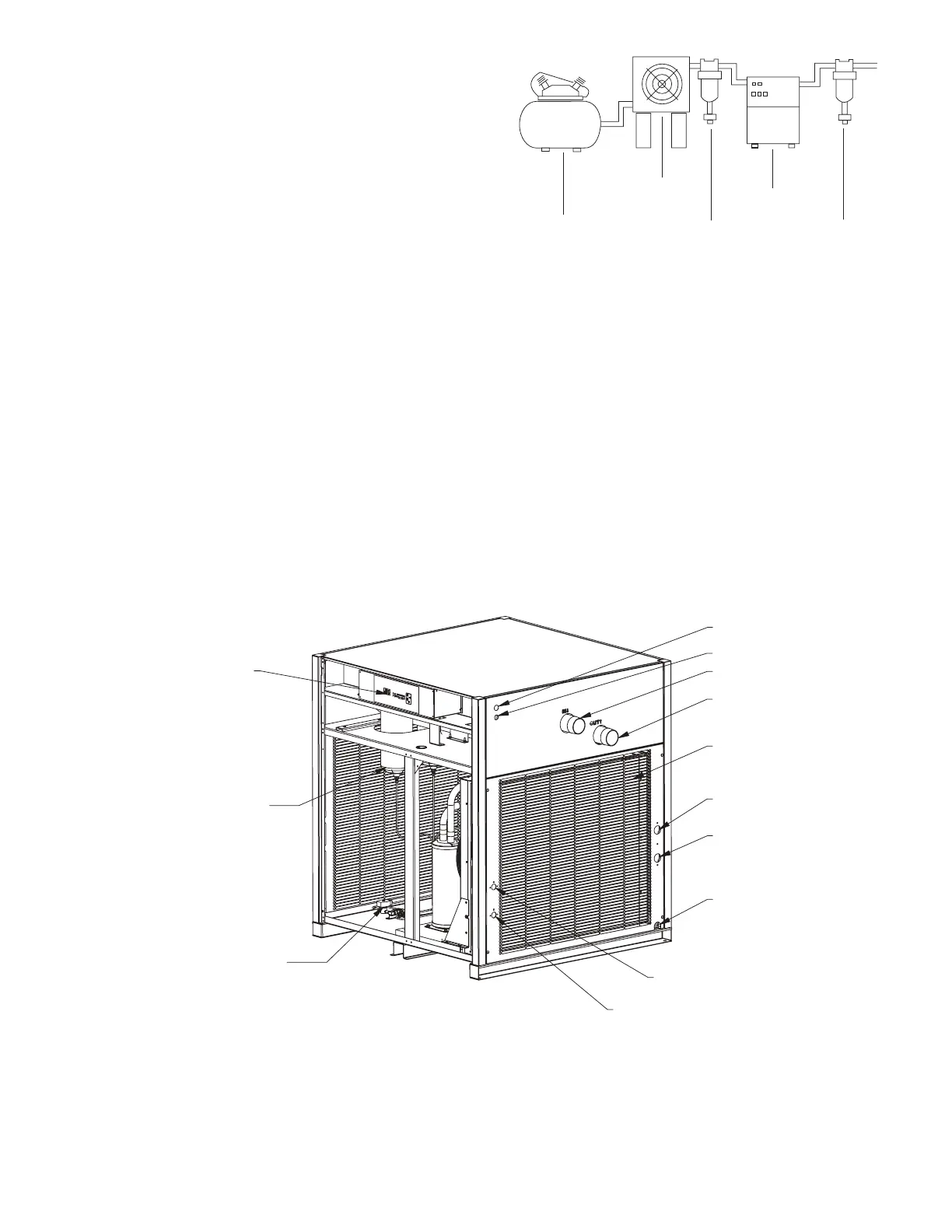
A. For typical placement in a compressed air system, see
drawing.
B. Aircompressorintake–Locateaircompressorsothat
contaminantspotentiallyharmfultothedryer(e.g.ammo-
nia)arenotdrawnintotheairsystem.
C. FreeAirFlow-Allowaminimumof36inches(914mm)
clearanceforfreeairow.
Service-Tofacilitatemaintenanceleave36inches
(914mm)ofclearanceinfrontofdryer.
D. Standard units are designed to operate in ambients:
Air-cooled:40to110°F(4to43°C).
Water-cooled:40to130°F(4to54°C).
E. Theinstallationofaexibleconnectionpriortothedryeris
recommendedtopreventpossibledamagefromvibration.
NOTE: Outdoorinstallation–Standardunitsaredesignedfor
indoorinstallation.Contactmanufacturerifinstallingoutdoors.
Aftercooler
Separator
Dryer
Oil Removal
Filter
Compressor
Air Inlet
Air Outlet
Condensor
Water Outlet Connection
6-10HP W/C Models Only
Water Inlet Connection
6-10HP W/C Models Only
Drain Outlet
Water Outlet Connection
4HP W/C Model Only
Water Inlet Connection
4HP W/C Model Only
Primary Electrical Entry
Secondary Electrical Entry
Control Panel
Moisture Separators
Electric Timed Drain Assembly
w/3-Way Valve
Models 4, 6, 7.5, and 10
 Loading...