4
1.2 Mounting
Mountthedryeronalevelsolidsurface.Holesareprovidedin
thedryerbasetopermanentlymountthedryertotheoor.
1.3 Piping Connections
A. AirInlet-Connectcompressedairlinefromairsource
toairinlet.(Referencemarkingsondryerorseecallout
drawingonpage13forairinlet/outletconnectionloca-
tions.)
NOTE: Customer piping needs to be properly supported.
Useback-upwrenchwhenmakingpipingconnections.
RefertoSerialNumberTagformaximum
workingpressure.Donotexceeddryer’sMaximumWorking
Pressure.
NOTE: Install dryer in air system at highest pressure possible
(e.g.beforepressurereducingvalves).
NOTE: Install dryer at coolest compressed air temperature
possible.Maximuminletcompressedairtemperature:120°F
(49°C).Ifinletairexceedsthistemperature,precooltheair
withanaftercooler.
B. AirOutlet–Connectairoutlettodownstreamairlines.
NOTE: Customer piping needs to be properly supported.
Useback-upwrenchwhenmakingpipingconnections.
C. Bypasspiping–Ifservicingthedryerwithoutinterrupting
the air supply is desired, piping should include inlet and
outlet valves and an air bypass valve.
D. Watercooledmodels–coolingwaterinletandoutlet
1. Connect cooling water supply to cooling water inlet.
2. Connect cooling water return line to cooling water
outlet connection.
NOTE: Strainer and water regulating valve are supplied on
water cooled models.
1.4 Electrical Connections
IMPORTANT: Use copper supply wires only.
A. Dryer is designed to operate on the volt-
age,phase,andfrequencylistedonthe
serial number tag.
B. Electrical entry on larger dryers is through
a hole in the cabinet. It is located on the right side panel
whenfacingthefrontoftheunit.Connectpowersource
to terminal strip in electrical enclosure as shown on the
wiring diagram included with the dryer.
NOTE:Refrigerationcondensingunitisdesignedtoruncon-
tinuously and should NOTbewiredtocycleon/offwiththeair
compressor.
1.5 Moisture Separator
A. Separatorhasanexternaldrainwhichauto-
matically discharges collected condensate.
NOTE: It may be desirable to pipe the con-
densatefromtheAutomaticDrainoutlettoa
suitable drain.
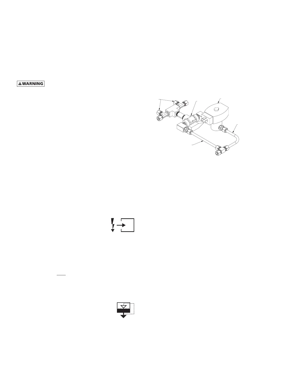
B. Formanualdraining,convenientdryerdepressurization,
and drain valve maintenance, a three-way valve assembly
is installed between the drain port on the moisture separa-
tor and the drain valve. On all models, the three-way
valveismountedtothebasepan.Reviewthefollowing
forproperdrainfunction:
• AutomaticDraining-Valvehandleshouldbepositioned
paralleltothevalvebody(asshown),withthearrow
on the handle pointing toward the drain valve. In this
position,condensatewillowfromthebowltothedrain
valve.
• DrainIsolation(Shutdown)-Valvehandleshallbe
turnedperpendiculartothevalvebody(rotate90°).In
thisposition,condensateowisshutoff.
Solenoid Valve
Automatic Discharge
Line
Manual Discharge Line
3-Way Valve
Drain Inlets
• ManualDraining-Drainvalvehandleshallberotated
slightly past the drain isolation position to allow
throttlingthroughthevalveformanualdischargeand
depressurization.
NOTE: Discharge is at system pressure. Drain line should be
anchored.
NOTE: Condensate may contain oil. Comply with applicable
laws concerning proper disposal.
 Loading...