EasyManua.ls Logo

HANKISON PR500 - User Manual

HANKISON PR500
20 pages
Print Icon
To Next Page IconTo Next Page
Loading...
1
7610.483.4B 8/01
INSTRUCTION MANUAL
Contents
GENERAL SAFETY INFORMATION ................................. 2
RECEIVING, MOVING, UNPACKING ............................... 2
1.0 INSTALLATION ........................................................ 3
2.0 OPERATION ........................................................... 6
3.0 MAINTENANCE ...................................................... 8
SIZING ........................................................................... 9
ENGINEERING DATA ..............................................10, 11
ELECTRICAL SCHEMATICS ......................................12, 13
CONTROL TRANSFORMER CONNECTIONS.................. 14
DIMENSIONS / WEIGHTS ............................................. 15
TROUBLESHOOTING .................................................... 16
PARTS LIST .............................................................17, 18
WARRANTY................................................................. 20
Models: PR500, PR600, PR700, PR800,
PR1000, PR1200, PR1600,
PR2000, and PR2300
SERVICE DEPARTMENT: (724) 746-1100
REFRIGERATED
TYPE
COMPRESSED
AIR DRYERS
®
IMPORTANT - 380-420V/3ph/50Hz models - control
transformer is wired to operate on a voltage range of 391
to 418. For voltages outside this range rewire transformer
as shown on page 12.
M
M
Question and Answer IconNeed help?

Do you have a question about the HANKISON PR500 and is the answer not in the manual?

Summary

General Safety Information

Pressurized Devices Safety

Safety precautions for operating the equipment as a pressure-containing device.

Electrical Safety Precautions

Safety guidelines for electrical connections and operation of the equipment.

Breathing Air Quality

Information regarding the suitability of treated air for breathing purposes.

Receiving, Moving, and Unpacking

Receiving Shipment Inspection

Procedure for inspecting incoming shipments for visible loss or damage.

Unpacking and Concealed Damage Check

Instructions for checking for concealed damage after unpacking.

Safe Moving Procedures

Guidelines for safely moving or transporting the dryer unit.

Storage and Shutdown Precautions

Important considerations for storing the unit and shutdown procedures.

Installation Guide

Optimal Installation Location

Guidance on selecting the best location for dryer placement in a system.

Mounting and Securing the Dryer

Instructions on how to mount the dryer on a firm level surface.

Piping Connections

Details on connecting air, condensate, and water lines.

Electrical Connections

Information on making electrical connections to the dryer.

Automatic Condensate Drain Operation

Procedures for operating and verifying automatic condensate drains.

Operation Guide

Operating Condition Limits

Specifies the minimum and maximum operating parameters for the dryer.

Dryer Start-up Procedure

Step-by-step instructions for starting up the dryer unit.

Periodic Operating Checks

Key points to check periodically to ensure proper dryer operation.

Digital Control Panel Functions

Explanation of the digital panel's displays and controls.

Shutdown and Restart Procedures

Procedures for safely shutting down and restarting the dryer.

Maintenance Schedule

Air-Cooled Model Maintenance

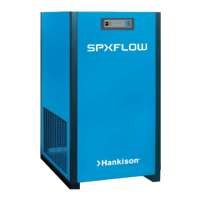
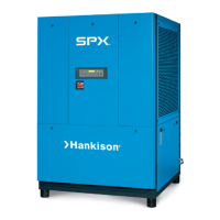
Maintenance tasks specific to air-cooled dryer models.

Water-Cooled Model Maintenance

Maintenance tasks specific to water-cooled dryer models.

Automatic Condensate Drain Maintenance

Maintenance procedures for automatic condensate drain systems.

Sizing and Capacity

Determining Dryer Capacity

How to determine maximum inlet flow capacity at various operating conditions.

Pressure Drop Calculation

How to determine pressure drop at increased flows using multipliers.

Engineering Data

Operating Condition Specifications

Minimum and maximum operating parameters for various models.

Refrigeration System Specifications

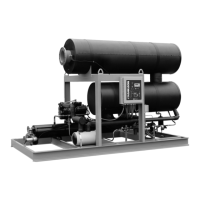
Details on the condensing unit, compressor, and refrigerant system.

Cooling Water Requirements

Water flow and pressure requirements for water-cooled models.

Electrical Specifications

Electrical data including voltage, amperage, and fuse sizes.

Electrical Connections

Customer Terminal Strip Connections

Wiring diagram for customer electrical connections on terminal strips.

Customer Entry Enclosure Connections

Wiring diagram for customer electrical connections in the entry enclosure.

Standard Control Panel Wiring Diagram

Detailed wiring diagram for the standard control panel.

Digital Control Panel Wiring Diagram

Detailed wiring diagram for the digital control panel.

Control Transformer Connections

Four Lead Transformer Wiring

Wiring diagrams for four-lead transformers (230 & 460V).

575 V Power Transformer Connection

Wiring diagram for 575V power transformer connections for 3 HP units.

Five Lead Transformer Wiring

Wiring diagrams for five-lead transformers (380-420V and 460/575V).

Dimensions and Weights

Physical Dimensions by Model

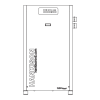
Detailed physical dimensions for each dryer model listed.

Weight Specifications by Model

Weight information for each dryer model, for air-cooled and water-cooled.

Troubleshooting Guide

Water Downstream Issues

Troubleshooting steps for water detected downstream of the dryer.

High Pressure Drop Issues

Troubleshooting steps for high pressure drop across the dryer.

High Temperature Alarm Issues

Troubleshooting steps for high temperature alarms.

Refrigeration System Issues

Troubleshooting common refrigeration system malfunctions.

Parts List

Parts List by Model and Voltage

Catalog of replacement parts cross-referenced by model and voltage.

Notes Section

Product Warranty Information

Warranty Terms and Conditions

Details on warranty coverage, duration, and exclusions.

Overview

This document is an instruction manual for Hankison refrigerated and compressed air dryers, covering models PR500, PR600, PR700, PR800, PR1000, PR1200, PR1600, PR2000, and PR2300. It provides essential information for installation, operation, maintenance, and troubleshooting of these devices.

Function Description

The Hankison air dryers are designed to remove moisture from compressed air, ensuring a lower dew point for downstream applications. This process is crucial for protecting pneumatic equipment and processes from the damaging effects of moisture, such as corrosion and freezing. The dryers utilize refrigeration technology to cool the compressed air, causing water vapor to condense and be removed.

Important Technical Specifications

The manual provides detailed technical specifications across various models and electrical configurations (208-230/3/60, 460/3-60, 200-220/3/50, 400/3/50, 575/3/60).

Operating Conditions:

  • Max. Inlet Air Pressure: 200 psig (14 bar) for most models, 300 psig (21 bar) optional.
  • Min. Inlet Air Pressure: 20 psig (1.4 kgf/cm²).
  • Max. Inlet Air Temperature: 120°F (49°C).
  • Max. Ambient Temperature (Air Cooled): 110°F (43°C).
  • Max. Ambient Temperature (Water Cooled): 130°F (54°C).
  • Min. Ambient Temperature: 35°F (2°C).
  • Outlet Air Temperature (nominal at rated conditions): 85°F (29°C).

Refrigeration System Data:

  • Compressor Type: Hermetic Non-Cycling (for 500-1000 models) or Hermetic Scroll / Non-cycling (for 1200-2300 models).
  • Refrigerant Type: R-134A (for 500-1000 models) or R-404A (for 1200-2300 models).
  • Rated Capacity (scfm): Ranges from 500 scfm (60Hz) for the PR500 to 2300 scfm (60Hz) for the PR2300.
  • Pressure Drop (psi) @ 100 psig inlet pressure, 100°F inlet temperature, and 100°F ambient temperature: Ranges from 3.2 psi to 5.0 psi depending on the model.
  • Cooling Water Requirements (water-cooled models): Recommended water pressure 40 Min. - 120 Max. psig. GPM of water @ 85°F cooling water ranges from 6/5 (60/50Hz) for PR500 to 35/30 (60/50Hz) for PR2300.

Electrical Data:

  • Nominal Voltage: Available in 208-230/3/60, 460/3-60, 200-220/3/50, 400/3/50, and 575/3/60 configurations.
  • Amperage Draw (Total Full Load): Varies significantly by model and voltage, e.g., 22.9A for PR500 (208-230/3/60) to 62.8A for PR2300 (208-230/3/60).
  • Unit Protection Fuse Size (amps): Ranges from 12-1/2A to 70A.
  • Branch Circuit Fuse Size (amps) Max.: Ranges from 20A to 125A.
  • Watts @ 35°F (1.7°C) Evaporator & 100°F (38°C) Ambient: Ranges from 2929W to 17490W.

Dimensions and Weights:

  • The manual includes a table with detailed dimensions (A-U) in inches and millimeters for all models, as well as weights for both air-cooled and water-cooled versions. Weights range from 912 lbs (414 kg) for the PR500 (air-cooled) to 2715 lbs (1232 kg) for the PR2300 (air-cooled).

Usage Features

Installation:

  • Location: Should be placed in a compressed air system as shown in the diagram. Air compressor intake should avoid drawing harmful contaminants. Air-cooled units require at least 36 inches (915 mm) clearance on either side for free airflow across the condenser.
  • Mounting: Mount on a firm, level surface. Shipping pads can be removed, and the dryer can be bolted to the floor. Standard dryers are for indoor installation; contact the manufacturer for outdoor use.
  • Piping Connections: Connect compressed air lines to inlet and outlet. Maximum working pressure must not be exceeded. Install the dryer at the highest possible pressure and coolest compressed air temperature. An aftercooler is recommended if inlet air exceeds 120°F (49°C). By-pass piping is recommended for servicing without interrupting air supply.
  • Condensate Drain: Manual petcocks are provided for draining. Automatic drains can be routed to a plant drainage system. Condensate may contain oil and must be disposed of according to applicable laws.
  • Water-cooled models: Connect cooling water supply and return lines. Strainer and water regulating valve are supplied.

Electrical Connections:

  • Use copper supply wires only. Unit operates on voltage, phase, and frequency listed on the serial number tag. Power source connects to a terminal strip in the electrical enclosure. The refrigeration condensing unit is designed for continuous operation and should not cycle on/off with the air compressor.
  • Control Panel: Models feature either a Standard Control Panel or a Digital Control Panel.
    • Standard Control Panel: Includes Power On (green), Compressor On (green), Refrigerant Pressure Cut Out (red), and High Temperature Warning (red) lights.
    • Digital Control Panel: Features a digital display for Lowest Air Temperature, Outlet Air Temperature, Ambient Temperature, Inlet Temperature Alarm set point, Lowest Air Temperature Alarm set point, and Electric Drain Closed time. It also has lights for Power On, Compressor On, Drain Energized, High Temperature Alarm, Mode Indicator, and an optional High Water Level Alarm. A drain test button is available for electric drains.

Start-up:

  • Energize the dryer disconnect switch 24 hours before starting the refrigeration compressor. Do not use the disconnect switch for extended shutdowns.
  • Start the unit before introducing air flow. Reset the high-pressure switch if the compressor off light illuminates.
  • For water-cooled units, start water flow through the condenser after 24 hours.
  • Position the on/off switch to "I" (on) after 24 hours.
  • For models 800-2300 with scroll compressors, verify proper compressor rotation by checking for unusual noise and suction pressure.

Operating Check Points (Periodic Basis):

  • Verify Power-on and Compressor-on lights are green.
  • Check that the High Air Temperature warning light is off (should extinguish within 15 minutes of start-up).
  • Ensure the Refrigerant Pressure Cut Out light is off.
  • Monitor suction and outlet pressure gauges for normal readings.
  • Check inlet temperature (should be below 120°F/49°C).
  • Verify condensate discharge from the drain.

Digital Panel Usage:

  • The numeric display shows various temperatures and alarm setpoints. The mode selector button allows cycling through different display parameters (Outlet Air Temperature, Ambient Temperature, Inlet Temperature Alarm set point, Lowest Air Temperature Alarm set point, Electric Drain Closed time, Inlet Air Temperature). Set points can be adjusted using up and down arrows.

Shutdown and Restart:

  • Shutdown: Turn the on/off switch to "O" (off), but leave the dryer energized unless servicing.
  • Restart: Ensure air inlet and outlet isolation valves are closed. Turn the on/off switch to "I" (on). Slowly open isolation valves and close the by-pass valve after 15 minutes.

Maintenance Features

Air-cooled models:

  • Condenser coil: Clean accumulated dust and dirt monthly. A blow-gun is supplied for this purpose; remove the condenser screen to access it.

Water-cooled models:

  • Strainer: Clean periodically to prevent water flow restriction.

Automatic condensate drains:

  • Daily Check: Verify automatic drain is discharging.
  • Weekly Manual Drain: Manually drain the separator.
  • Electric Drains: Periodically clean the strainer in drain reservoirs.
  • Mechanical Drains: Rebuild drain mechanisms annually using repair parts kit 05.7501-03.

Troubleshooting Guide

The manual includes a comprehensive troubleshooting guide for common issues:

  • Water downstream of dryer: Possible causes include residual moisture in pipelines, open air by-pass, reversed connections, low ambient temperatures, excessive bulk liquid at inlet, clogged drains, improper electric drain timer settings, dryer overload, or refrigeration system malfunction. Corrective actions range from blowing out the system with dry air, checking valve positions, insulating air lines, installing a separator, rebuilding drain mechanisms, resetting electric drain timers, to checking temperatures and pressures.
  • High pressure drop across dryer: Can be caused by excessive air flow or freezing moisture in the evaporator due to refrigeration system malfunction. Corrective actions involve checking flow rate and addressing refrigeration system issues.
  • High Temperature Alarm: May result from dryer overload causing high air outlet temperature, refrigeration system malfunction, or a malfunctioning thermostatic switch. Corrective actions include checking for overload, addressing refrigeration system issues, or contacting a qualified repairman.
  • Refrigeration system not functioning properly:
    • Power on light off: Indicates power failure, open disconnect switch, blown fuses, open breaker, faulty wiring, or loose terminals. Corrective actions involve checking power, switches, fuses, and electrical connections.
    • Refrigerant Suction Pressure Gauge in red area: Suggests the refrigeration compressor is not running, high inlet/ambient air temperature, or incorrect compressor rotation (for 800-2300 models). Corrective actions include contacting a repairman, checking temperatures, and verifying compressor rotation.
    • Refrigerant Suction Pressure Gauge in blue area: Points to an improperly set hot gas by-pass valve or low refrigerant levels. Corrective action is to contact a repairman.
    • Refrigerant pressure cut out light on: Can be due to high/low ambient temperature, dirty/clogged condenser fins (air-cooled), obstructed airflow, non-functioning fan motor/switch (air-cooled), high/low cooling water temperature, low flow, faulty water regulating valve, clogged strainer (water-cooled), or a tripped high-pressure switch during start-up. Corrective actions include checking ambient temperature, cleaning condensers, checking water flow/temperature, cleaning strainers, and manually resetting the switch.

Warranty

The manufacturer warrants the product to be free from defects in material and workmanship for one year from shipment to the buyer or 18 months from factory shipment, whichever occurs first. For refrigerated dryers (25-2300 scfm), the warranty is two years from factory shipment. The warranty covers parts and labor for 18 months and parts only for an additional six months for these specific dryers. Unauthorized service voids the warranty. The maximum liability is the original purchase price. The warranty is exclusive and in lieu of all other warranties, including implied warranties of merchantability and fitness for a particular purpose. The manufacturer is not liable for incidental or consequential costs. Authorization from the service department is required before returning material or performing in-warranty repairs.

HANKISON PR500 Specifications

General IconGeneral
BrandHANKISON
ModelPR500
CategoryDehumidifier
LanguageEnglish

Related product manuals